
Main transmission mechanism of high-speed punching machine

A technology of high-speed punching machine and main drive, which is applied to the driving device of punching machine, press machine, forging press, etc. It can solve the problems of small inertial force, damaged punching accuracy, and degradation of punching accuracy, and achieve easy balance of inertial force , reduce wear and temperature rise, and improve accuracy retention

Pending Publication Date: 2019-03-08
CHANGZHOU TEXTILE GARMENT INST
View PDF7 Cites 0 Cited by
  • Summary
  • Abstract
  • Description
  • Claims
  • Application Information

AI Technical Summary

Problems solved by technology

[0003] The stamping speed of the traditional punching machine is low and the inertial force is small. Compared with the traditional punching machine, although the stamping speed is increased, the inertial force is also increased synchronously; if the moving parts cannot achieve dynamic balance, the inertial force will periodically affect the high-speed punching machine Exciting force, which causes the vibration of the high-speed punching machine, which eventually leads to damage to the punching machine and affects the punching accuracy
In addition, most of the traditional mechanical punching machines use the slider crank mechanism. The speed and acceleration of the slider in the working stroke are large and difficult to adjust, which cannot provide a long forming time for the stamping of the workpiece; and, the modified punch slider It also bears the force in the horizontal direction, which makes the slider guide rail easy to wear, resulting in rapid degradation of stamping accuracy

Method used


Image

  • Main transmission mechanism of high-speed punching machine

Examples


Embodiment Construction

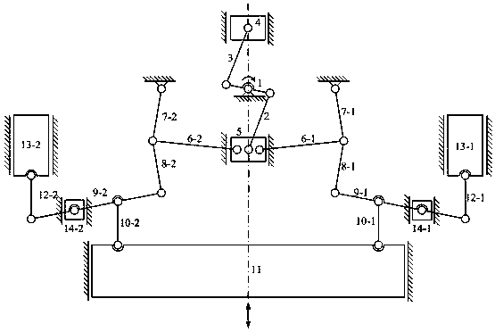
[0017] Attached below figure 1 The preferred embodiments of the present invention are described in detail, so that the advantages and features of the present invention can be more easily understood by those skilled in the art, so as to define the protection scope of the present invention more clearly.

[0018] In order to better realize the inertial force balance of the main transmission mechanism of a high-speed punch press, the present invention discloses a main transmission mechanism of a high-speed punch press. One end of a double crank 1 with a phase angle difference of 180 degrees is connected to an auxiliary slider 4 through an auxiliary connecting rod 3 , and the other One end is connected with the moving slider 5 through the main connecting rod 2, and the auxiliary slider 4 and the moving slider 5 move linearly on the guide rail. When working, the motor drives the double crank 1 to rotate, and the double crank 1 drives the auxiliary slider 4 and the moving slider 5 to...


PUM


Abstract

The invention discloses a main transmission mechanism of a high-speed punching machine. One ends of double cranks, the phase angle difference between which is 180 degrees, are connected by an auxiliary connecting rod and an auxiliary sliding block, and the other ends of the double cranks are connected by a main connecting rod and a moving sliding block; the double cranks are connected to a motor;the auxiliary sliding block and the moving sliding block linearly move on a vertical guide rail; a left multi-bar mechanism and a right multi-rod mechanism which have the same structure are symmetrically arranged at the left side and right side of the moving sliding block; and the moving sliding block is connected to a punching sliding block through the two multi-bar mechanisms. The auxiliary connecting rod and the auxiliary sliding block of the main transmission mechanism disclosed by the invention balance the inertial force of the main connecting rod and the moving sliding block to the greatest extent; the multi-bar mechanisms which are symmetrical left and right not only have the obvious force-increasing effect, but also reduce the abrasion of the punching sliding block and the guide rail; a lever mechanism adopted in the main transmission mechanism has the force-increasing effect; a balance sliding block balances the inertia force of the punching sliding block to the greatest extent; and the adjustment of the dead center position under the punching sliding block can be realized by changing the position of an adjusting sliding block.

Description

technical field [0001] The invention relates to the technical field of high-speed punching machines, in particular to a main transmission mechanism of high-speed punching machines. Background technique [0002] As a high-efficiency forging equipment, high-speed punches have been widely used in important industrial fields such as aerospace, automobile manufacturing, transportation, metallurgy and chemical industry. Especially in recent years, the rapid development of the manufacturing industry led by automobiles has greatly promoted the progress of my country's stamping industry. With the acceleration of market globalization, the competition in the same industry is becoming more and more fierce. In order to improve production efficiency and reduce production costs, users have put forward higher requirements for stamping speed. The birth of high-speed punching machines just meets the needs of the market. [0003] The stamping speed of the traditional punching machine is low a...

Claims


Application Information

Patent Timeline
Patent Type & Authority Applications(China)
IPC IPC(8): B30B1/06B30B1/14B21J9/18
CPCB21J9/18B30B1/06B30B1/14
Inventor 陈浩张蔚权洁马晓明
Owner CHANGZHOU TEXTILE GARMENT INST
Learn More