Workbench for broaching machine tool

A workbench and machine tool technology, applied in the field of CNC machine tools, can solve the problems of high requirements for processing equipment, cumbersome processing processes, labor and time-consuming efficiency, etc., and achieve the effect of reducing processing equipment requirements, ensuring processing quality, and reducing production costs.

Pending Publication Date: 2019-03-08
ZHEJIANG CHR INTELLIGENT EQUIP
View PDF2 Cites 11 Cited by
  • Summary
  • Abstract
  • Description
  • Claims
  • Application Information

AI Technical Summary

Problems solved by technology

[0003] The tenons and grooves of aircraft turbine disk workpieces of different specifications often have different inclination angles α or cone angles β, such as Figure 1-Figure 2 As shown, the inclination angle α of the tenon groove of the turbine disk refers to the angle formed by the deflection of the tenon groove on the outer peripheral surface of the turbine disk workpiece relative to the axis line of the turbine disk. The taper angle β of the tenon groove of the turbine disk workpiece is Refers to the angle between the outer peripheral surface of the turbine disk workpiece and the axis line of the turbine disk. Since the broach can only move in a straight line, it is necessary to prepare a tooling fixture with a corresponding angle when using a broaching machine to process this type of workpiece. When broaching the broaching of turbine disk workpieces with different specifications, different fixtures need to be replaced. The processing process is very cumbersome, time-consuming and inefficient
In addition, the milling method can also be used to form the tenon and groove of the turbine disk workpiece. However, when using a forming milling cutter to process such a disk workpiece with an outer contour tooth shape or a groove shape with an inclination angle and a cone angle, it is necessary to use Multi-axis machining centers also have the problems of high requirements for processing equipment and low processing efficiency

Method used


Image

  • Workbench for broaching machine tool
  • Workbench for broaching machine tool
  • Workbench for broaching machine tool

Examples


Embodiment Construction

[0027] The present invention will be further described in detail below in conjunction with the accompanying drawings and embodiments.

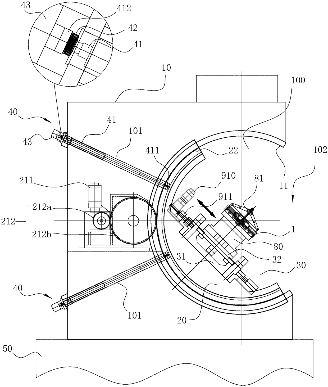
[0028] see Figure 3-Figure 11, the workbench applied to the broaching machine tool includes a fixed base 10, an arc-shaped sliding seat 20 and a sliding table mechanism 30, wherein the sliding table mechanism 30 is arranged on the arc-shaped sliding seat 20, and the arc-shaped sliding seat 20 is slidably connected On the fixed base 10 , wherein the workpiece to be processed is fixed on the sliding table mechanism 30 and can rotate together with the arc-shaped sliding seat 20 . The arc-shaped chute 100, the inner wall of the arc-shaped chute 100 is an arc-shaped wall recessed inward from top to bottom, wherein, the outer wall surface of the arc-shaped sliding seat 20 is the same as the arc-shaped wall of the arc-shaped chute 100. On the curved surface with the same radian size, two first curved guide rails 11 are correspondingly arranged on t...


PUM


Abstract

The invention relates to a workbench for a broaching machine tool. The workbench comprises a fixed base and an arc-shaped sliding seat, and further comprises a sliding table mechanism for fixing a to-be-machined workpiece; an arc-shaped sliding groove is formed in the fixed base, and the arc-shaped sliding seat is mounted in the arc-shaped sliding groove; a first arc-shaped guide rail is correspondingly arranged on the inner wall of the arc-shaped sliding groove, and the arc-shaped sliding seat is slidably connected to the first arc-shaped guide rail and can be locked with the fixed base in the process of sliding along the first arc-shaped guide rail so as to stay at any tilt angle; the sliding table mechanism is slidably arranged on the arc-shaped sliding seat; and a locking mechanism forlocking the sliding table mechanism and the arc-shaped sliding seat is arranged between the sliding table mechanism and the arc-shaped sliding seat. According to the workbench, a turbine disc can beprecisely adjusted to the corresponding machining posture through driving mechanisms of shafts, then the workpiece is conveniently machined by a cutter, a tooth shape or a groove shape with the corresponding tilt angle and cone angle is formed, the machining efficiency of the workbench is greatly improved, the production cost is lowered, and the machining quality is guaranteed.

Description

technical field [0001] The invention relates to the technical field of numerical control machine tools, in particular to a workbench for broaching machine tools. Background technique [0002] The broaching machine tool can be used for broaching of different workpieces. During broaching, the workpiece to be processed is fixed on the worktable of the broaching machine tool through the fixture, and then the surface of the workpiece is shaped by the linear reciprocating action of the broaching tool For example, the tenon and groove of aircraft turbine disk workpieces are often processed by broaching. [0003] The tenons and grooves of aircraft turbine disk workpieces of different specifications often have different inclination angles α or cone angles β, such as Figure 1-Figure 2 As shown, the inclination angle α of the tenon groove of the turbine disk refers to the angle formed by the deflection of the tenon groove on the outer peripheral surface of the turbine disk workpiece r...

Claims


Application Information

Patent Timeline
Patent Type & Authority Applications(China)
IPC IPC(8): B23D41/00B23Q1/25
CPCB23D41/00B23Q1/25
Inventor 林绿高
Owner ZHEJIANG CHR INTELLIGENT EQUIP
Why Eureka
Try Eureka