High-speed motor dynamic balance self-adjusting device

A high-speed motor and self-adjusting technology, applied in electromechanical devices, electric components, manufacturing motor generators, etc., can solve problems such as complicated and inaccurate adjustment processes of dynamic balance

Inactive Publication Date: 2019-03-05
张峰
View PDF4 Cites 3 Cited by
  • Summary
  • Abstract
  • Description
  • Claims
  • Application Information

AI Technical Summary

Problems solved by technology

[0004] The technical problem solved by the present invention is that the adjustment of the existing dynamic balan...

Method used


Image

  • High-speed motor dynamic balance self-adjusting device
  • High-speed motor dynamic balance self-adjusting device

Examples


Embodiment 1

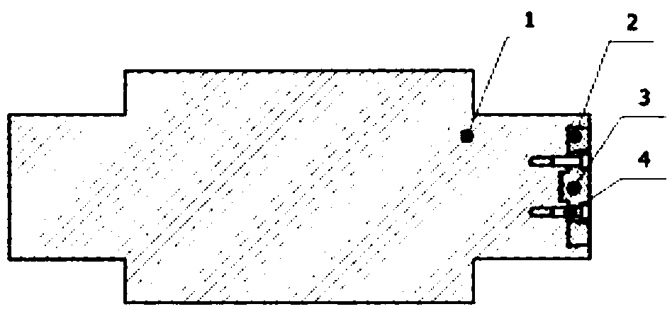
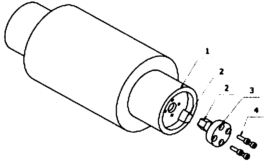
[0015] As shown in the figure: the high-speed motor dynamic balance self-adjusting device, including the rotating shaft, counterweight, fixed plate and locking parts, the rotating shaft is connected with the rotating shaft of the motor, and the counterweight is connected to the fixed plate and locked by the locking parts On the rotating shaft, the counterweights are evenly distributed circumferentially around the rotating shaft. The rotating shaft has a dovetail structure, and the fixing plate is provided with a dovetail groove matching the rotating shaft. The counterweight is an annular column structure. Mounting holes are uniformly arranged on the fixed plate

[0016] In this embodiment, the entire breeding device is placed outside the motor, so that the dynamic balance of the entire motor can be adjusted anytime and anywhere. We only need to calculate the weight to be mated during the running and calibration process, and then add and lock the mating we need on the fixed p...

Embodiment 2

[0018] As shown in the figure: the high-speed motor dynamic balance self-adjusting device, including the rotating shaft, counterweight, fixed plate and locking parts, the rotating shaft is connected with the rotating shaft of the motor, and the counterweight is connected to the fixed plate and locked by the locking parts On the rotating shaft, the counterweights are evenly distributed circumferentially around the rotating shaft. The rotating shaft has a dovetail structure, and the fixing plate is provided with a dovetail groove matching the rotating shaft. The counterweight is an arc-shaped block structure. Mounting holes are uniformly arranged on the fixed plate

[0019] During implementation, the entire breeding device is placed outside the motor, so that the dynamic balance of the entire motor can be adjusted anytime and anywhere. We only need to calculate the weight to be mated during the running and calibration process, and then add and lock the mating we need on the fi...


PUM


Abstract

The invention belongs to the technical field of motor dynamic balance, and particularly relates to a high-speed motor dynamic balance self-adjusting device. The device comprises a rotating shaft, weight balancing blocks, a fixed plate and a locking piece, wherein the rotating shaft is connected with a self-contained rotating shaft of the motor; the weight balancing blocks are connected with the fixed plate and are locked to the rotating shaft through the locking piece, and the weight balancing blocks are evenly distributed around the rotating shaft in the circumferential direction. The whole weight balancing device is externally arranged outside the motor, so that the dynamic balance of the whole motor can be adjusted anytime and anywhere. The weight required to be balanced is calculated only in the process of running and correcting, and then the weight balancing and locking are carried out on the fixed plate, so that the weight balancing can be rapidly completed. According to the structure, the whole motor is not required to be detached, and a dynamic balance test is carried out independently. Meanwhile, the dynamic balance of the motor during operation is ensured. The weight balancing blocks are convenient to machine and easy to realize standardization. The structure is wide in application range, and can be popularized to other rotary equipment to be used for correcting dynamic balance.

Description

technical field [0001] The invention belongs to the technical field of motor dynamic balance, in particular to a high-speed motor dynamic balance self-adjusting device. Background technique [0002] During the production and manufacturing process of the existing motor rotor, due to the impact of structural form, process method and assembly scheme, the rotor will have an unbalanced amount. The poor dynamic balance of the rotor will increase the vibration and noise of the whole equipment and shorten the life of the supporting bearing. Especially in high-speed and ultra-high-speed motor applications, the influence of the rotor's dynamic balance on the motor is very large. [0003] At present, the speed of the rotor of a general high-speed motor is higher than 10,000 rpm. Once the rotor is unbalanced, it will cause strong vibration of the motor during operation, and it will cause fluctuations in the air gap between the rotor and stator of the motor, which will affect the stabi...

Claims


Application Information

Patent Timeline
IPC IPC(8): H02K15/16
CPCH02K15/165
Inventor 张峰
Owner 张峰
Why Eureka
Try Eureka