
Novel reactive power consumption structure optimization device for anode carbon block of electrolytic cell

An anode carbon block and electrolytic cell technology, which is applied to the carbon field of aluminum electrolysis, can solve the problems of increasing resistance, reducing the gross consumption of carbon blocks, wasting power consumption, etc., so as to reduce gross consumption, reduce pollution and reduce production costs. Effect

Inactive Publication Date: 2019-03-05
吴中华
View PDF0 Cites 0 Cited by
  • Summary
  • Abstract
  • Description
  • Claims
  • Application Information

AI Technical Summary

Problems solved by technology

Since the use of anode carbon blocks in my country's electrolytic cells, experts have continuously improved the quality and appearance structure. The appearance structure improvements include single slots, double slots, vertical slots, four-corner cuts, eight-sided cuts, horizontal string holes, Heightening and lengthening the carbon block, etc., no matter what improvements have been made, the gross consumption of the carbon block has not been reduced. Up to now, the average carbon block gross consumption per ton of aluminum produced by the electrolytic cell is 485kg, accounting for 13.2% of the production cost. The anode life cycle is 32 days, from From the perspective of the entire production cost structure, only the carbon consumption index has room for reduction. If the quality of the carbon block is improved, the production cost of the anode carbon block will be increased. If the height or length of the anode carbon block can be extended, the negative impact will be brought It is the increase of the resistance that wastes power consumption. In this fiercely competitive market, no carbon manufacturer is willing to improve the quality without increasing the cost. How to make the anode Reducing carbon consumption is currently the main topic of research and development by all experts

Method used


Image

  • Novel reactive power consumption structure optimization device for anode carbon block of electrolytic cell
  • Novel reactive power consumption structure optimization device for anode carbon block of electrolytic cell

Examples


Embodiment Construction

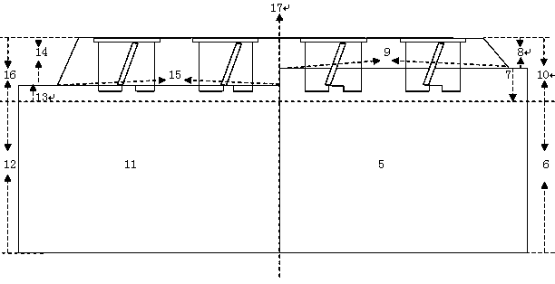
[0010] like figure 2 Shown: A new structure optimization device for the reactive power consumption of the anode carbon block in the electrolytic cell, which optimizes the structure of the boss and the carbon block between the top and bottom of the anode carbon block 170mm ( figure 2 16 in), the height of the boss is changed from the original 70mm ( figure 2 8) optimized to 140mm ( figure 2 13 in), the anode carbon block under the boss is 100mm ( figure 2 7) optimized to 30mm ( figure 2 12 in), the width of the lower side of the boss is 600mm ( figure 2 9) reduced to 480mm ( figure 2 14), the anode density is changed from the original 1.58 g / cm 3 Increased to 1.62 g / cm 3 .

[0011] The boss and carbon block structure between the anode carbon block 170mm from top to bottom is the height of the reactive power consumption of the anode carbon block, which is called the height of the residual electrode by electrolytic workers, and is also the height of the structural ...


PUM

PropertyMeasurementUnit
heightaaaaaaaaaa
heightaaaaaaaaaa

Abstract

The invention provides a novel reactive power consumption structure optimization device for an anode carbon block of an electrolytic cell. According to the reactive power consumption structure optimization effect of the anode carbon block of the electrolytic cell, the weight of a boss is increased to 76 kg from the original 30 kg, the weight of the anode carbon block below the boss is decreased to54 kg from the original 180 kg, the weight after structure optimization is reduced to 130 kg by 80 kg compared with the weight before optimization, and the average ton of aluminum is reduced by 37 kg. The structure optimization is very obvious for reducing the gross consumption of the anode carbon block, the gross consumption index of the entire anode carbon block is changed, and a foundation islaid for enterprises to reduce production cost. As the residual maximum dose of the reactive power consumption is greatly reduced, the transportation volume is reduced, and environmental pollution isreduced.

Description

technical field [0001] The invention relates to the technical field of carbon in aluminum electrolysis, in particular to a structure optimization device for reactive power consumption of anode carbon blocks of a novel electrolytic cell. Background technique [0002] The anode carbon block is a product of the carbon factory, mainly used for the anode conductor of the electrolytic cell. It is called the heart of the electrolytic cell by the aluminum industry. The quality and appearance of the anode carbon block directly affect the service life and production of the aluminum electrolytic cell. cost. Since the use of anode carbon blocks in my country's electrolytic cells, experts have continuously improved the quality and appearance structure. The appearance structure improvements include single slots, double slots, vertical slots, four-corner cuts, eight-sided cuts, horizontal string holes, Heightening and lengthening the carbon block, etc., no matter what improvements have bee...

Claims


Application Information

Patent Timeline
Patent Type & Authority Applications(China)
IPC IPC(8): C25C3/12
CPCC25C3/125
Inventor 吴中华吴怡梦吴克飞吴凯王晓娟
Owner 吴中华
Learn More