
Constant speed sampling device of boiler water working medium

A constant velocity sampling and boiler water technology, applied in the direction of sampling devices, sampling, measuring devices, etc., can solve the problem that the sample composition does not fully represent the overall working medium, and achieve the effect of reducing the difficulty of debugging, reducing costs, and ensuring sample quality

Pending Publication Date: 2019-03-01
SHANGHAI BOILER WORKS
View PDF10 Cites 0 Cited by
  • Summary
  • Abstract
  • Description
  • Claims
  • Application Information

AI Technical Summary

Problems solved by technology

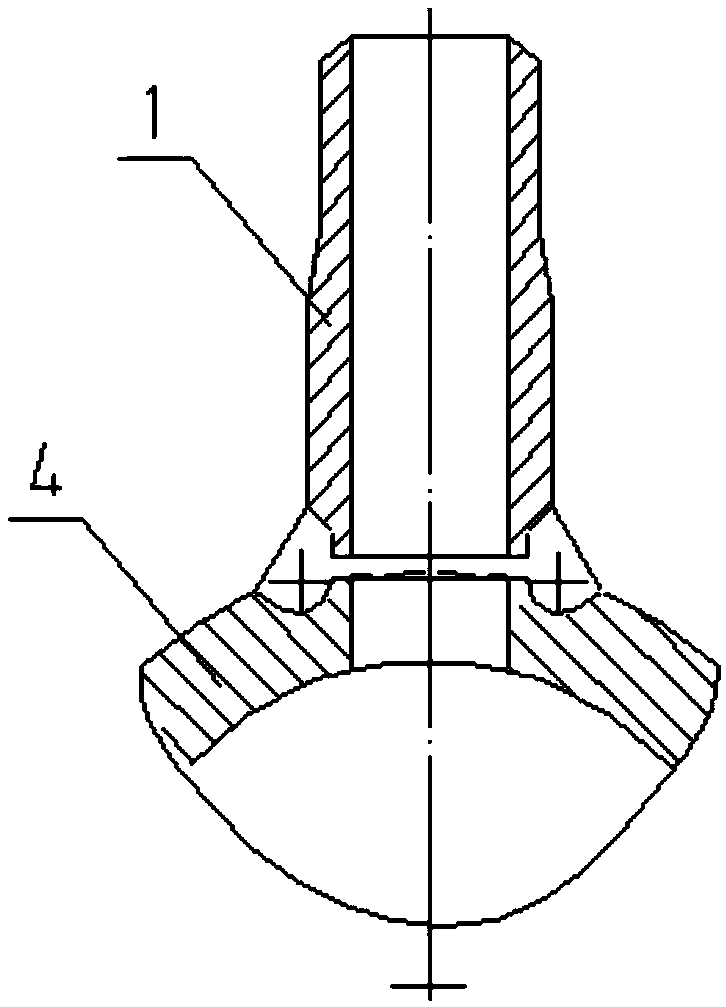
[0006] figure 1 Shown is the existing boiler feed water sampling structure, the boiler feed water sampling is directly drawn from the pipe joint (sampling pipe 1) on the main pipe 4, the water working fluid drawn out in this way will include fluid boundary layer impurities, and it is not a constant velocity sampling, the sample composition Does not fully represent the overall working medium

Method used


Image

  • Constant speed sampling device of boiler water working medium
  • Constant speed sampling device of boiler water working medium
  • Constant speed sampling device of boiler water working medium

Examples


Embodiment Construction

[0028] Below in conjunction with specific embodiment, further illustrate the present invention.

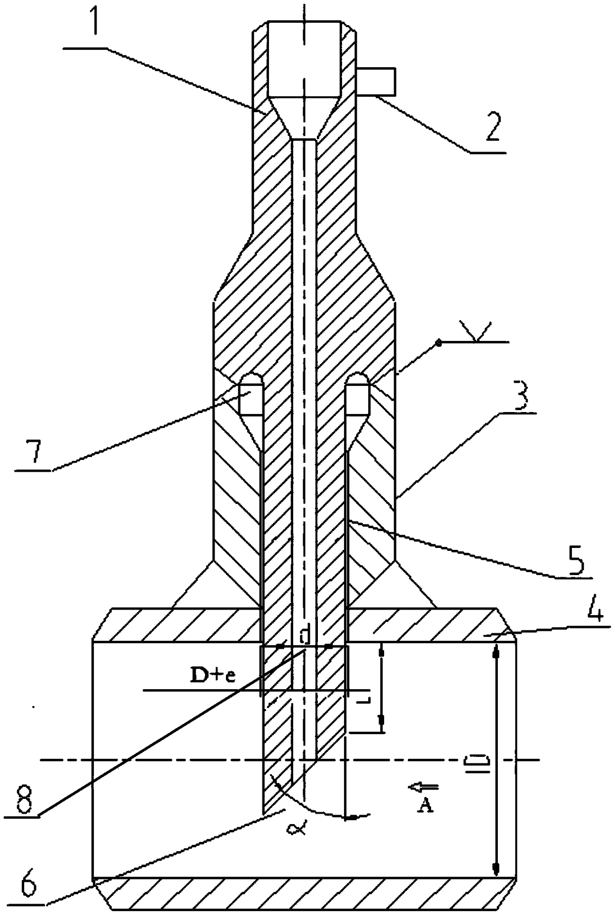
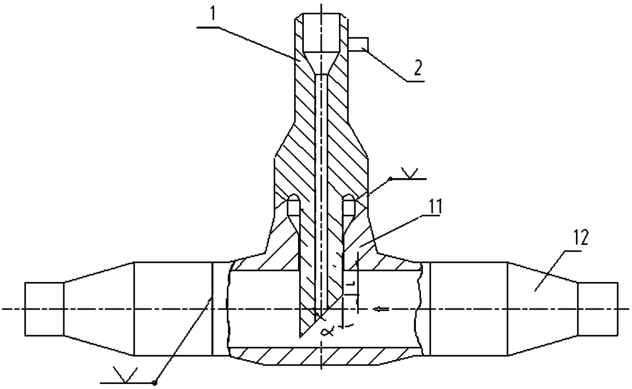
[0029] figure 2 It is a schematic diagram of a boiler hydraulic fluid constant-kinetic sampling device. The boiler hydraulic fluid constant-kinetic sampling device includes a sampling tube 1, a sign 2, a transition tube 3, a main tube 4, etc., wherein the bottom end of the transition tube 3 is connected to the main tube 4 The walls are connected vertically, and the top of the transition pipe 3 is butt-welded with the middle of the sampling pipe 1. The pipe wall of the main pipe 4 has a hole, and the lower end of the sampling pipe 1 passes through the transition pipe 3 and is inserted into the main pipe 4 . The upper end of the sampling pipe 1 is welded with an indicating steel plate 2 .

[0030] The upper end of the transition pipe 3 is provided with a flaring opening 7 to provide a gap required for material expansion during welding. The inner diameter of the root of the trans...


PUM


Abstract

The invention provides a constant speed sampling device of a boiler water working medium. The bottom end of a transition pipe is connected with the pipe wall of a main pipe; the top end of the transition pipe is butt-welded with the middle part of a sampling pipe; the lower end of the sampling pipe penetrates through the transition pipe and is inserted into the main pipe; the inner diameter of thesampling pipe is calculated according to constant speed sampling requirements; a slope surface for guiding the working medium to enter the sampling pipe from the front side is formed obliquely at thebottom of the sampling pipe against the flow direction of the working medium in the main pipe; and an indication steel plate for examining the direction of the slope surface of the sampling pipe during assembling for rotating the sampling pipe in place, and enabling the slope surface and an open pore at the bottom of the sampling pipe to over against the flow direction of the working medium is arranged at the upper end of the sampling pipe. By arranging the slope surface, the contact cross-sectional area between the sampling device and the working medium is reduced, the phenomenon of ruptureat the contact position due to vibration and the like is reduced, the rigidity of the sampling device is improved, technical requirements of constant speed sampling are met, and the safety and accuracy of the sampling device in an operation process are enhanced. The sampling device has simple structure, is convenient to manufacture and assemble, and is applicable to constant speed sampling of theboiler water working medium.

Description

technical field [0001] The invention relates to a constant velocity sampling device for boiler hydraulic fluid, which is used for constant velocity sampling of boiler drum sewage and boiler feed water, and belongs to the technical field of boiler pressure parts. Background technique [0002] In the process of boiler operation, in addition to strict monitoring of steam quality, there are also strict requirements on boiler water quality. This requires that some samples taken from the main hydraulic fluid be representative. After real-time sampling and analysis, the power plant adjusts the steam-water medium in time according to the sample quality to ensure the normal operation of the boiler and steam turbine. Critical factors in a sampling system include: sampling point, material selection, system design, sampling time, sampling frequency, and proper procedures to maintain sample integrity prior to sample analysis. With the development of the industry and the stricter produc...

Claims


Application Information

Patent Timeline
Patent Type & Authority Applications(China)
IPC IPC(8): G01N1/10
CPCG01N1/10G01N2001/1031
Inventor 洪梅安保睿洪慧周曙光沙招根
Owner SHANGHAI BOILER WORKS
Learn More