Micromechanical electrostatic driven linear comb structure

An electrostatic drive and comb-tooth structure technology, which is applied in the direction of microelectronic microstructure devices, microstructure technology, microstructure devices, etc., can solve the problems of reducing the driving voltage of the structure, achieve a large driving stroke, reduce weight, and increase the cavity volume effect

Active Publication Date: 2019-03-01
BEIJING INST OF AEROSPACE CONTROL DEVICES
View PDF11 Cites 2 Cited by
  • Summary
  • Abstract
  • Description
  • Claims
  • Application Information

AI Technical Summary

Problems solved by technology

[0003] Invention patent application "A Comb Structure Driven by Micromechanical Electrostatics" (Application No. 201410440148.7) proposes that the shape of the comb adopts a combination of triangle and trapezoid, or a combination of triangle and rectangle, or a combination of trapezoids, reducing The driving voltage of the structure, but it is only applicable to the driving mode in which the driving displacement is perpendicular to the comb direction

Method used


Image

  • Micromechanical electrostatic driven linear comb structure
  • Micromechanical electrostatic driven linear comb structure

Examples


Embodiment Construction

[0021] Below in conjunction with accompanying drawing and specific embodiment the present invention is described in further detail:

[0022] The invention provides a micro-mechanical electrostatically driven linear comb structure, which achieves a larger driving stroke under the same vacuum environment and driving voltage as the traditional technology, without increasing the difficulty of the process.

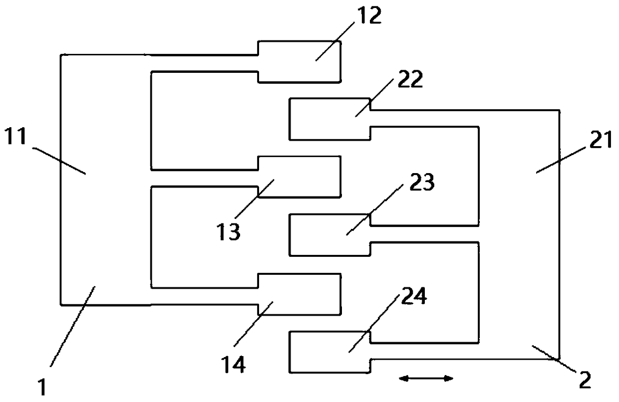
[0023] Such as figure 1 Shown is a schematic diagram of a linear comb group. It can be seen from the figure that a micro-mechanical electrostatically driven linear comb structure includes n groups of the same linear comb group; n groups of linear comb groups are evenly distributed on the outside On the horizontal side wall of the device; each group of linear combs includes static combs (1) and dynamic combs (2); the static combs 1 and the dynamic combs 2 are E-shaped structures that are interlaced; the static combs A voltage is applied between 1 and the moving comb 2, under th...


PUM


Abstract

The invention discloses a micromechanical electrostatic driven linear comb structure and relates to the technical field of micromechanical electrostatic drive. The structure comprises n groups of samelinear combs, wherein the n groups of linear combs are horizontally and uniformly distributed on a horizontal side wall of an external device; each group of linear combs comprise a static comb and adynamic comb; the static comb and dynamic comb are staggered E-shaped structures. Under external electrostatic drive, the dynamic comb carries out linear motion close to or away from the static comb along the horizontal side wall of the external device. When the static comb matches the dynamic comb, a first movable electrode stretches into a position between a first fixed electrode and a second fixed electrode, a second movable electrode stretches into the position between the second fixed electrode and a third fixed electrode, and a third movable electrode is set at the outer side of a thirdfixed electrode. According to the structure, under a vacuum environment and a drive voltage the same as those of a conventional technology, relatively long drive travel is obtained, and technologicaldifficulty is not increased.

Description

technical field [0001] The invention relates to the technical field of micro-mechanical electrostatic drive, in particular to a linear comb structure for micro-mechanical electrostatic drive. Background technique [0002] Electrostatic drive is an important method of micro-mechanical drive technology, and it is widely used in the current MEMS field. At present, the most common structure in the electrostatic driving structure is a rectangular planar comb array structure. However, the current rectangular comb-tooth electrostatic driver has the problems of relatively small driving force and too high driving voltage. However, the application occasions of micro-electromechanical devices often have upper limit requirements on the driving voltage, and it is hoped to reduce the driving voltage as much as possible or increase the driving displacement. The common way to solve this contradiction is to increase the number of comb teeth to form an array. The disadvantage of increasing...

Claims


Application Information

Patent Timeline
Patent Type & Authority Applications(China)
IPC IPC(8): B81B3/00B81B7/02
CPCB81B3/0021B81B7/02B81B2201/033B81B2201/035
Inventor 庄海涵杨静刘福民刘国文
Owner BEIJING INST OF AEROSPACE CONTROL DEVICES
Why Eureka
Try Eureka