A gasket separation device with oiling function
What is Al technical title?
Al technical title is built by PatSnap Al team. It summarizes the technical point description of the patent document.
A separation device and gasket technology, which is applied to the surface coating liquid device, cleaning device, coating, etc., can solve the problems of cumbersome operation of the gasket separation device, gaskets sticking together, low work efficiency, etc., to achieve Easy to take, reliable positioning, high work efficiency
Active Publication Date: 2020-08-04
江苏择善精密机械有限公司
View PDF7 Cites 0 Cited by
Summary
Abstract
Description
Claims
Application Information
AI Technical Summary
This helps you quickly interpret patents by identifying the three key elements:
Problems solved by technology
Method used
Benefits of technology
Problems solved by technology
[0002] The main function of the gasket is to increase the contact area between the bolt or nut and the surface of the part, prevent the surface of the part from being worn out, and play the role of fastening and anti-loosening. When the gasket is used, the phenomenon that the gasket often sticks together. In the actual production process, it is easy to take more, take more and add more gaskets, etc., resulting in quality problems. Commonly used gasket separation devices are cumbersome to operate, complex in structure, and low in work efficiency.
Method used
Image
Click on the blue label to locate the original text in one second.
Reading with bidirectional positioning of images and text.
Examples
Embodiment
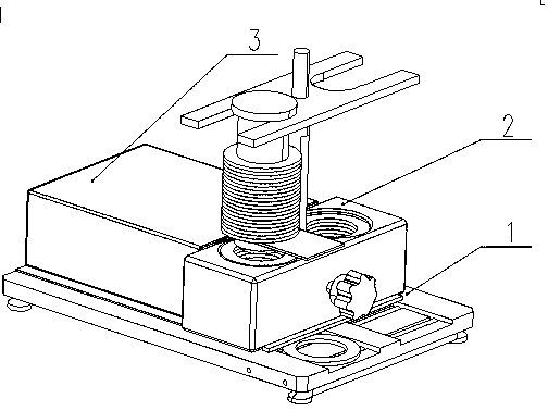
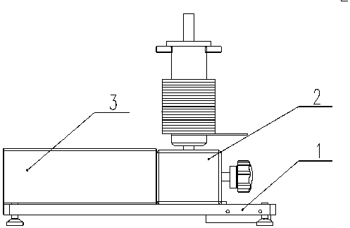
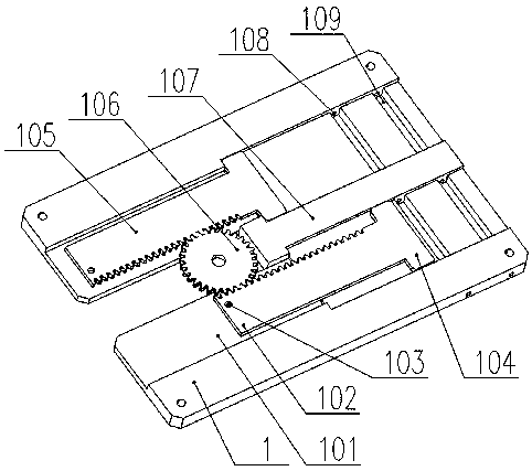
[0028] Such as figure 1 , figure 2 , image 3 , Figure 4 , Figure 5 , Figure 6 , Figure 7 , Figure 8 , Figure 9 , Figure 10 as well as Figure 11As shown, a gasket separation device with an oiling function includes a bottom plate 1, a sinker 101, a first rack 102, a mounting hole 103, a first rack 104, a second rack 105, a gear 106, and a T-shaped Fixed block 107, rotating shaft hole 108, oil groove 109, rotating shaft 110, cylinder 111, cylinder fixing plate 112, connecting rod 113, connecting pin 114, L-shaped bracket 115, mandrel 116, positioning plate 117, fixing seat 118, feeding seat 2 , feeding hole 201, flat hole 202, transition rod 203, notch 204, gasket 205, charging rod 206, feeding positioning plate 207, second hanging table 208, stop piece 209, torx screw 210, baffle plate 211 , ball 212, chamber 213, oil inlet 214, square pin 215, cylindrical pin 216, square hole 218, anti-off block 219, U-shaped opening 220 and cover plate 3, and the upper end ...
PUM
Abstract
The invention provides a gasket separation device with the oil coating function. The gasket separation device comprises a bottom plate, a countersink groove, a first rack, a mounting hole, a first hanging table, a second rack, a gear, a T-shaped fixed block, rotary shaft holes, an oil groove, a rotary shaft, a cylinder, a cylinder fixing plate, a connecting rod, a connecting pin, an L-shaped support, a central spindle, a locating plate, a fixed seat, a feed seat, a feed hole, a flat hole, a transition rod, a notch, gaskets, a gasket feed rod, a feed locating plate, a second hanging table, a stop piece, a Torx screw, a baffle, roll balls, a cavity, an oil inlet hole, a square cotter, a cylindrical pin, a square hole, an anti-off block, U-shaped openings and a cover plate. A gear is welded and fixed to the bottom end of the central spindle. The bottom of the countersink groove is provided with the oil groove and the roll balls. The gear and the racks conduct driving. Through the gasket separation device, the problems that excessive gaskets are taken and added during production are solved. Moreover, the gasket separation device has the gasket separation and automatic oil coating functions and also has the characteristics of being high in working efficiency, convenient to use and the like.
Description
technical field [0001] The invention relates to the technical field of gasket processing and manufacturing, in particular to a gasket separating device with an oiling function. Background technique [0002] The main function of the gasket is to increase the contact area between the bolt or nut and the surface of the part, prevent the surface of the part from being worn out, and play the role of fastening and anti-loosening. When the gasket is used, the phenomenon that the gasket often sticks together. In the actual production process, it is easy to take more, take more and add more gaskets, etc., resulting in quality problems. Commonly used gasket separation devices are cumbersome to operate, complex in structure and low in efficiency. Contents of the invention [0003] In view of the above problems, the present invention provides a gasket separation device with an oiling function. The device adopts a gear and rack structure, and uses the left and right movement of the cyl...
Claims
Application Information
Patent Timeline
Application Date:The date an application was filed.
Publication Date:The date a patent or application was officially published.
First Publication Date:The earliest publication date of a patent with the same application number.
Issue Date:Publication date of the patent grant document.
PCT Entry Date:The Entry date of PCT National Phase.
Estimated Expiry Date:The statutory expiry date of a patent right according to the Patent Law, and it is the longest term of protection that the patent right can achieve without the termination of the patent right due to other reasons(Term extension factor has been taken into account ).
Invalid Date:Actual expiry date is based on effective date or publication date of legal transaction data of invalid patent.
