Positive-pressure discharge device capable of being conveniently cleaned
An air-closing and cleaning technology, applied in the field of air-closing, can solve the problems of time-consuming, low quality of new materials, inconvenient cleaning, etc., and achieve the effect of reducing labor force, improving work efficiency and convenient operation.
- Summary
- Abstract
- Description
- Claims
- Application Information
AI Technical Summary
Problems solved by technology
Method used
Image
Examples
Embodiment 1
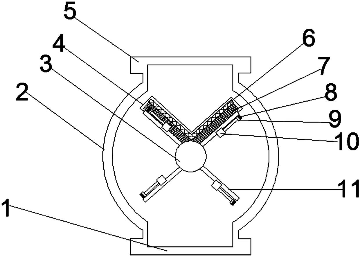
[0030] refer to Figure 1-2 , the present invention provides a positive pressure air lock that is easy to clean, including the air lock housing 2, the feed port 5 and the discharge port 1 connected to the air lock housing 2, and the air lock housing 2 The internal rotating shaft 3, the blades 11 connected to the rotating shaft 3, and the driving mechanism for driving the rotating shaft 3 to rotate. The inside of the air lock housing 2 perpendicular to the rotating shaft 3 is connected with a cleaning mechanism. The groove 4 inside the housing 2 is connected with a telescopic mechanism, the telescopic mechanism is connected with a connecting plate 6 perpendicular to the rotating shaft 3, and the connecting plate 6 is connected with a bristle-7.
[0031] Working principle: When using the easy-to-clean positive pressure air lock provided by this application, after use, drive the rotating shaft 3 to rotate through the driving mechanism, so that the blades 11 connected to the rotat...
Embodiment 2
[0034] refer to Figure 1-2 , based on embodiment 1, the connection plate 6 of this embodiment is an "L" shaped structure, the groove 4 is also an "L" shaped structure, and the surface of the connection plate 6 facing the blade 11 is connected with a bristle one 7.
[0035] Since the tank in the air lock is formed by two adjacent blades 11, this application sets the connecting plate 6 as an "L"-shaped structure, on the face of the "L"-shaped connecting plate 6 and the blades 11. Connect the bristle 7 to achieve the effect of cleaning the blades 11 on both sides of the same tank at one time during the cleaning process, which shortens the cleaning time by half and greatly improves the cleaning efficiency; the groove 4 is also set to "L" The shape structure is to make the connecting plate 6 just enter the inside of the groove 4, which will not affect the normal use of the air lock, and at the same time reduce the footprint of the groove 4. Wherein the connecting plate 6 of the ...
Embodiment 3
[0037] refer to Figure 1-2 , based on Embodiment 1, the telescopic mechanism of this embodiment includes a through hole 17 arranged in the groove 4, a push rod 13 is movably pierced in the through hole 17, one end of the push rod 13 is connected with the connecting plate 6, and the other end of the push rod 13 is One end extends to the outside of the air lock housing 2 and is connected with a drive mechanism 2 12 that drives the push rod 13 to expand and contract.
[0038] When a cleaning operation is required, the telescopic movement is driven by the drive mechanism 2 12, so that the connecting plate 6 connected to the push rod 13 can be moved back and forth, and then the bristles connected to the connecting plate 6 are bonded to the blade 11. The residual material is brushed until loose to achieve the cleaning effect. It is easy to operate, more stable during the driving process, and the cleaning effect is better. It has the function of protecting the equipment and prolongi...
PUM
 Abstract
Description
Claims
Application Information
 - R&D Engineer
- R&D Manager
- IP Professional
- Industry Leading Data Capabilities
- Powerful AI technology
- Patent DNA Extraction
Browse by: Latest US Patents, China's latest patents, Technical Efficacy Thesaurus, Application Domain, Technology Topic, Popular Technical Reports.
© 2024 PatSnap. All rights reserved.Legal|Privacy policy|Modern Slavery Act Transparency Statement|Sitemap|About US| Contact US: help@patsnap.com


