Piezoelectric fan heat dissipating closed module

A piezoelectric fan, closed technology, applied in the direction of cooling/ventilation/heating transformation, electrical components, electrical equipment structural parts, etc. Achieve the effect of simple structure, wide environmental adaptability and strong electromagnetic compatibility

Inactive Publication Date: 2019-02-26
SICHUAN JIUZHOU ELECTRIC GROUP
View PDF10 Cites 2 Cited by
  • Summary
  • Abstract
  • Description
  • Claims
  • Application Information

AI Technical Summary

Problems solved by technology

The above heat dissipation methods have the following disadvantages: 1. Forced air cooling is a common heat dissipation method adopted by the chassis
The method is to install an air-cooled cold plate inside the chassis, such as the invention with the patent number 201020013244.0 and the name "multi-channel ATR airtight chassis cooling device". The traditional axial fan is used to cool and dissipate the chassis. The disadvantage is that the chassis is bulky. , high noise, long and narrow air duct, high wind resistance, low fan reliability, and low service life
2. The space constraint of secondary cooling equipment required by traditional liquid-cooled chassis often becomes its restrictive design factor
3. When the heat of the module is transferred to the cold plate of the chassis through the wall rail conduction, due to the existence of thermal resistance, the heat conduction efficiency is low and the heat dissipation effect is not good

Method used


Image

  • Piezoelectric fan heat dissipating closed module
  • Piezoelectric fan heat dissipating closed module

Examples


Embodiment 1

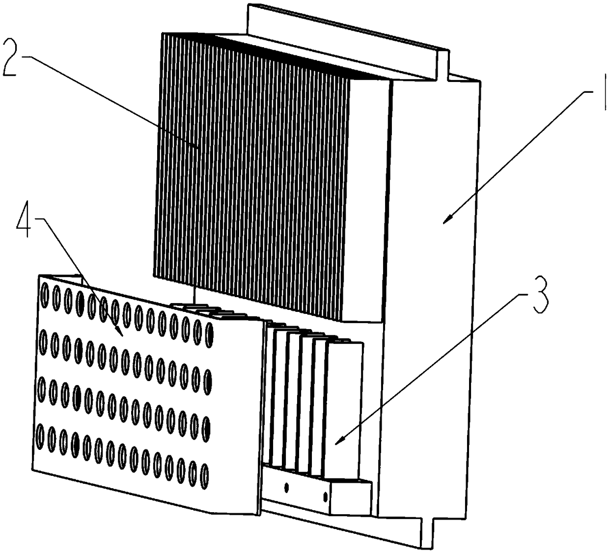
[0033] Such as figure 1 As shown, a piezoelectric fan heat dissipation closed module of the present invention includes,

[0034] Module 1, cooling fins 2 and piezoelectric fan 3. The cooling fins 2 are arranged on the cavity wall of the module 1, and the piezoelectric fan 3 is arranged below the cooling fins 2 to provide cooling airflow for the cooling fins 2.

[0035] In this embodiment, the heat dissipation fins 2 and the blades of the piezoelectric fan 3 are in a parallel structure, and the piezoelectric fan 3 uses the inverse piezoelectric effect of piezoelectric ceramics to drive the blades directly under the driving of an alternating electric field. Resonance is generated, and the high-speed and stable airflow is output from the blade end to the front to directly cool the parts that need heat dissipation.

[0036] In this embodiment, a temperature equalization device is provided in the base plate of the heat dissipation fin 2, which can be a VC equal temperature plate o...

Embodiment 2

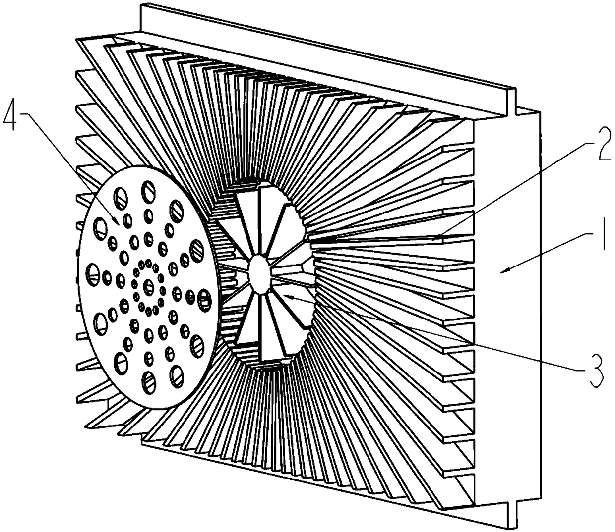
[0041] Such as figure 2 As shown, it is another embodiment of the piezoelectric fan cooling airtight module of the present invention, including a module 1, cooling fins 2 and a piezoelectric fan 3, and the cooling fins 2 are arranged on the cavity wall of the module 1, and implemented The difference from Example 1 is that in this embodiment, the cooling fins 2 are in a structure surrounded by sunflowers, the blades of the piezoelectric fan 3 are also in a structure surrounded by sunflowers, and the piezoelectric fan 3 is installed on the top of the cooling fins 2. at the center. The piezoelectric fan 3 utilizes the inverse piezoelectric effect of piezoelectric ceramics. Driven by an alternating electric field, the blades resonate, and output high-speed and stable airflow from the blade end to the surrounding cooling fins 2 . A protective cover plate 4 is provided on the outside of the piezoelectric fan 3, and an air inlet hole is provided on the cover plate 4.

[0042] Comp...


PUM


Abstract

The invention provides a piezoelectric fan heat dissipating closed module, comprising: a module; heat dissipating fins disposed on a cavity wall of the module or disposed on a cover plate of the module, used for cooling a heating component in the module; a piezoelectric fan, disposed adjacent to the heat dissipating fins, used for providing cooling airflow to the heat dissipating fins. The piezoelectric fan heat dissipating module performs air-cooling heat dissipation on the module, and does not depend on a cold plate of a chassis. Compared with a module of a traditional fan, the module has wider working temperature, small volume, and low noise, and has no electromagnetic interference. The module is exquisite in structure, and has a flexible embedded design, and can realize more efficientheat dissipation in smallest volume.

Description

technical field [0001] The invention relates to the technical field of case heat dissipation, in particular to a piezoelectric fan heat dissipation closed type module. Background technique [0002] With the improvement of the functions of electronic equipment, the integration and heat flux density of the devices are also significantly improved, such as power modules, power amplifier modules, integrated modules, etc. Heat dissipation management ensures the reliability of the equipment. [0003] Due to the requirements of electromagnetic compatibility and anti-harsh environment, most modules adopt a closed structure design. Traditional modules usually adopt the heat dissipation method of wall rail conduction, that is, the heat of the module is conducted to the cold plate of the chassis through the locking strip, and then The case is cooled by forced air or liquid cooling. The above-mentioned heat dissipation method has the following disadvantages: 1. Forced air cooling is a ...

Claims


Application Information

Patent Timeline
Patent Type & Authority Applications(China)
IPC IPC(8): H05K7/20
CPCH05K7/20154H05K7/20172
Inventor 李丽丹张庆军刘压军何钊
Owner SICHUAN JIUZHOU ELECTRIC GROUP
Why Eureka
Try Eureka