Cooling device for centrifugal machine pouring

A technology of cooling device and centrifuge, which is applied in the field of cooling device for centrifuge pouring, can solve the problems of long operation time, low efficiency, and affecting the quality of workpiece forming, and achieve good cooling effect and improved cooling effect

Inactive Publication Date: 2015-03-18
YANGZHOU YIFENG BRONZE PROD
View PDF0 Cites 1 Cited by
  • Summary
  • Abstract
  • Description
  • Claims
  • Application Information

AI Technical Summary

Problems solved by technology

[0002] The traditional cooling method is to cast first, then disassemble and demold, and spray water for cooling. The operation process takes a long time and the efficiency is low, so that the expected effect and purpose of cooling cannot be achieved.
[0003] The above cooling method is because the cooling is completed after pouring, and the overcooling is delayed, resulting in the optimal cooling time of the workpiece has passed, so it will affect the molding quality of the workpiece

Method used


Image

  • Cooling device for centrifugal machine pouring

Examples


Embodiment Construction

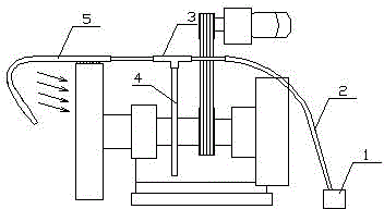
[0011] The present invention includes a water pump 1, the water pump 1 is connected to a regulating valve 3 through a water inlet pipe 2, and the regulating valve 3 is connected to a spray pipe 5 above a workpiece through a pipe.

[0012] The regulating valve 3 is fixed by a fixing bracket 4 .

[0013] The shower pipe 5 includes a front shower pipe arranged directly above the workpiece and a side shower pipe arranged on the side of the workpiece. The nozzles of the side shower pipe are arranged obliquely and are arranged on one side of the workpiece.

[0014] The water inlet pipe 2 of the present invention adopts a hose to facilitate the arrangement of the water inlet pipe 2; the nozzle of the side spray pipe of the present invention is arranged obliquely, which has an impact force on the side of the workpiece, further strengthening the cooling effect.

[0015] In the present invention, a temperature sensor can be installed near the workpiece, and a receiver can be installed o...


PUM


Abstract

The invention relates to a cooling device for centrifugal machine pouring. The cooling device for the centrifugal machine pouring comprises a water pump, the water pump is connected with a regulating valve through a water inlet pipe, and the regulating valve is connected with a spray pipe located above a workpiece through a pipeline. When performing centrifugal pouring, the cooling device for the centrifugal machine pouring cools the workpiece through enabling water to pass through the spray pipe through the water pump, in order to improve the cooling effect, the spray pipe simultaneously cools the upside and lateral surfaces of the workpiece, because the workpiece rotates, the cooling device for the centrifugal machine pouring is capable of fully cooling the workpiece, and the cooling effect is good; the regulating valve can regulate the water flow rate and flow speed according to practical situations so as to guarantee the best cooling effect for the workpiece.

Description

technical field [0001] The invention relates to a cooling device for centrifuge pouring, which is applied to the device for cooling the workpiece while the centrifuge is pouring the workpiece. Background technique [0002] The traditional cooling method is to cast first, then disassemble and demould, and spray water for cooling. The operation process takes a long time and the efficiency is low, so the expected effect and purpose of cooling cannot be achieved. [0003] The above-mentioned cooling method is because the pouring is completed and then cooled, and the overcooling is delayed, resulting in the optimal cooling time of the workpiece has passed, so it will affect the molding quality of the workpiece. Contents of the invention [0004] The present invention aims at the above-mentioned defects and aims to provide a cooling device for centrifuge pouring which can cool workpieces during centrifugal pouring. [0005] To this end, the technical solution adopted by the pre...

Claims


Application Information

Patent Timeline
Patent Type & Authority Applications(China)
IPC IPC(8): B22D13/10B22D30/00
CPCB22D13/10B22D30/00
Inventor 何叶锋
Owner YANGZHOU YIFENG BRONZE PROD
Why Eureka
Try Eureka