
Transformer differential protection method based on variable window length integral of sudden change sampling value

A differential protection and transformer technology, applied in the direction of emergency protection circuit devices, electrical components, etc., can solve problems such as unfavorable transformer shocks, and achieve the effects of improving operation speed, high computing efficiency, and protection operation reliability

Active Publication Date: 2019-02-26
INTEGRATED ELECTRONICS SYST LAB
View PDF5 Cites 6 Cited by
  • Summary
  • Abstract
  • Description
  • Claims
  • Application Information

AI Technical Summary

Problems solved by technology

At present, the differential quick-break protection of transformers usually adopts protection algorithms such as current full-cycle differential Fourier and small vector algorithm. This kind of algorithm needs to meet a certain length of data window to calculate and judge, and because the fixed value is fixed, the protection action time is basically the same as The severity of the fault is irrelevant, which is not conducive to reducing the impact on the transformer when a large current fault occurs

Method used


Image

  • Transformer differential protection method based on variable window length integral of sudden change sampling value
  • Transformer differential protection method based on variable window length integral of sudden change sampling value
  • Transformer differential protection method based on variable window length integral of sudden change sampling value

Examples


Embodiment Construction

[0040] The specific embodiments of the present invention will be described in detail below in conjunction with the accompanying drawings.

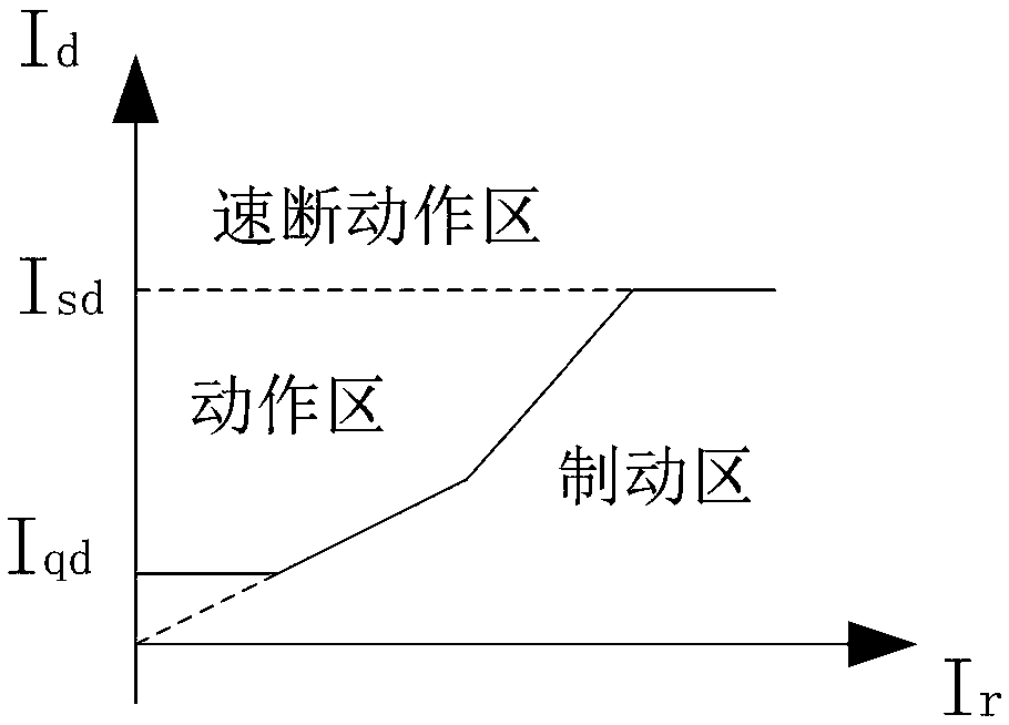
[0041] Such as figure 1 Shown is a schematic diagram of a typical differential protection action curve for transformer protection. In the figure, Id is the differential current, Iqd is the differential start setting value, Isd is the differential quick-break current setting value, and Ir is the braking current. The invention mainly considers that the differential protection quickly operates to remove the fault in the case of a serious fault, that is, the action range is the quick-break action area in the schematic diagram. The action formula is as follows:

[0042]

[0043] Where: The differential current of the transformer is calculated from the vector sum of the currents on each side. The more serious the fault The larger the value;

[0044] Isd is the setting value of the transformer differential quick-break current, usually set at 5 to 1...


PUM


Abstract

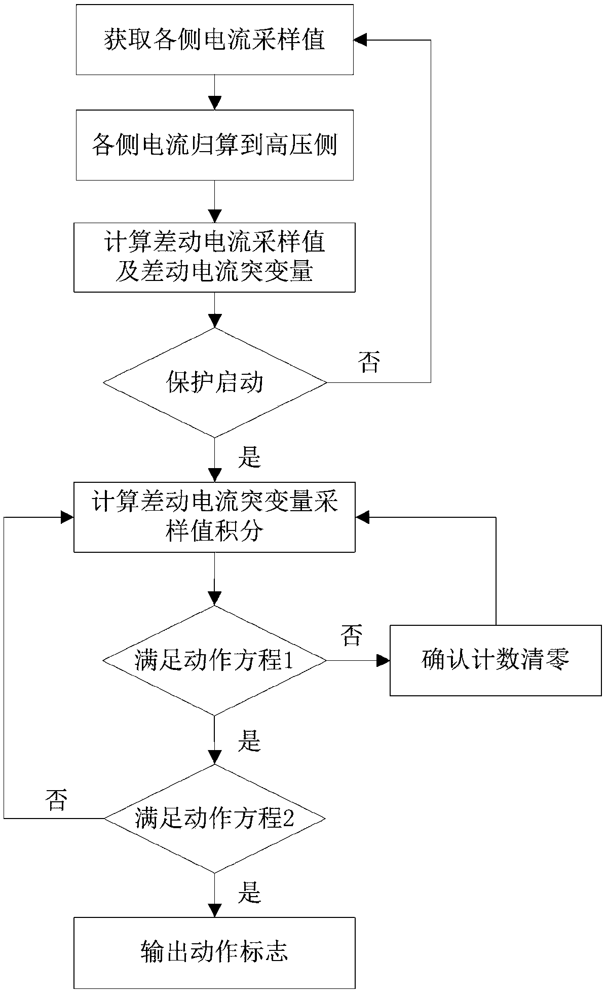
The invention relates to a transformer differential protection method based on a variable window length integral of sudden change sampling values. A current sample value of each side is obtained through a current transformer of each side of a transformer, the reduction of the currents on other sides of the transformer are conducted on the high voltage side, a differential current sample value anda differential current sudden change amount are obtained through calculation, and the differential current sudden change amount is used to judge whether protection is started or not, and the differential current sudden change amount sample value integral is calculated to judge whether the differential current sudden change amount sample value integral satisfies the condition, and the confirmationcount N1 is accumulated to judge whether the accumulated N1 satisfies the condition. The method improves the action speed of the differential protection, realizes the inverse time limit characteristicof the differential protection, reduces the data cache and the resource occupation, has high operation efficiency and is easy to realize in a device.

Description

Technical field [0001] The invention belongs to the technical field of power transformer automation management, and specifically relates to a transformer differential protection method based on a variable window length integral of a mutation amount sampling value. Background technique [0002] As an important equipment of the power system, the power transformer will have a serious impact on the normal power supply and equipment safety of the power supply system when it fails. Therefore, a protective device must be installed in the transformer to protect it. [0003] The main protection of the transformer is generally the longitudinal differential protection. Because the longitudinal differential protection needs to identify the inrush current and over-excitation operation status of the transformer, when a serious fault occurs inside the transformer, the fault cannot be quickly removed, which is important for the stable operation of the power system Bring serious harm, so it is nece...

Claims


Application Information

Patent Timeline
Patent Type & Authority Applications(China)
IPC IPC(8): H02H7/045
CPCH02H7/045
Inventor 李波王秀广刘益青冯占华刘志利
Owner INTEGRATED ELECTRONICS SYST LAB
Learn More