Roller vacuum drying machine with cooling section

A drum vacuum and cooling section technology, applied in the direction of dryers, drying, non-progressive dryers, etc., can solve the problems of large heat loss, etc., and achieve the effects of increasing firmness, avoiding impact and swing, and good sealing effect

Inactive Publication Date: 2019-02-26
程长青
View PDF0 Cites 0 Cited by
  • Summary
  • Abstract
  • Description
  • Claims
  • Application Information

AI Technical Summary

Problems solved by technology

[0003] The hot air convection drying is 4000-7500kj/kg, because convection drying requires hot air to heat the material, and t...

Method used


Image

  • Roller vacuum drying machine with cooling section
  • Roller vacuum drying machine with cooling section
  • Roller vacuum drying machine with cooling section

Examples


Embodiment

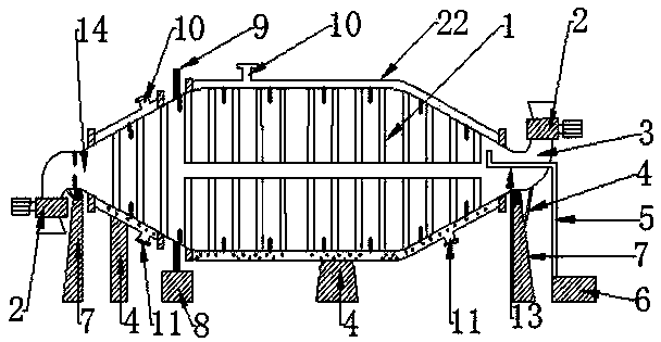
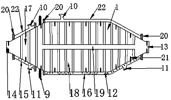
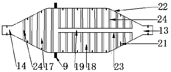
[0131] Such as figure 1 , figure 2 , Figure 6 , Figure 7 A drum vacuum dryer with a cooling section shown includes a drum drying chamber (1), a discharge device (2), an elbow (3), a bracket (4), an air duct (5), a vacuum unit (6 ), supporting wheel bracket (7), driving device (8), gear ring (9), sealing device (20), hopper (29).

[0132] The drum drying chamber (1) includes a heating chamber (16), a cooling chamber (15), a drying chamber (19), a sealing device (20), and a heat conducting medium (12).

[0133] The drum drying bin (1) has an inlet (13) and an outlet (14); the inlet (13) and outlet (14) on the drum drying bin (1) are also drying bins (19 ) feed port (13), discharge port (14).

[0134] Such as figure 1 Shown support roller support (7) comprises support, support roller.

[0135] 1. The supporting wheel is installed on the bracket.

[0136] 2. The roller support (7) supports the drying chamber (19) supporting the drum drying chamber (1).

[0137] The bra...


PUM

PropertyMeasurementUnit
Diameteraaaaaaaaaa
Lengthaaaaaaaaaa
Diameteraaaaaaaaaa

Abstract

The invention discloses a roller vacuum drying machine with a cooling section. The roller vacuum drying machine comprises a roller drying bin, an unloading device, an elbow, a support, an air guide pipe, a vacuum unit, a riding wheel support, a driving device, a gear ring, a sealing device and a material hopper. The roller drying bin comprises a heating bin, a cooling bin, a drying bin, a sealingunit and a heat conduction medium. The riding wheel support supports the drying bin of the roller drying bin. The gear ring drives the drying bin to do rotation movements under the effect of the driving device. The end, without a flange, of the elbow and a material inlet and outlet of the roller drying bin are in sealed connection into a whole through the sealing device. One end of the unloading device is fixedly connected with the flange on the elbow. The other end of the unloading device is provided with the material hopper. One end of the air guide pipe is connected to the vacuum unit. Theother end of the air guide pipe penetrates through the elbow and extends into the roller drying bin. Materials in the drying section are heated by the heat energy in the heating bin, the heat converting efficiency is high, loss is small, the dried materials are cooled in the cooling section, and the heat energy released during material cooling can also be used as waste heat; when a certain heat pipe is damaged and leakage happens, the use of the whole roller vacuum drying machine with the cooling section is not influenced.

Description

technical field [0001] The invention relates to a drum dryer, in particular to a drum vacuum dryer with a cooling section. Background technique [0002] Nowadays, materials such as grain, food, chemical industry, medicine, agricultural and sideline products, pasture and so on need to be heated and dried in the field of processing and production; most of the drying chambers of the drying equipment on the market are heat-exchanged with row-type heat-dissipating standpipes However, their radiators have large volume, small heat dissipation area, and low efficiency of heat energy use. If the heat dissipation riser in the drying chamber leaks, it is not easy to repair, which will cause the tumble dryer to be scrapped and cannot be used. The heating device of the tumble dryer is installed on the drying site of the tumble dryer, which reduces the use efficiency of the drying site of the tumble dryer and causes environmental pollution of the drying site of the tumble dryer. The mat...

Claims


Application Information

Patent Timeline
IPC IPC(8): F26B5/04F26B11/04F26B23/10F26B25/00F26B25/02
CPCF26B5/04F26B11/0481F26B23/10F26B25/007F26B25/008F26B25/02Y02P70/10
Inventor 程长青
Owner 程长青
Why Eureka
Try Eureka