
Rotor pump shaft sealing device

A shaft seal, rotor pump technology, applied in pump components, rotary piston type/swing piston type pump components, machines/engines, etc., can solve problems such as affecting the service life of the rotor pump, affecting, not fundamentally eliminating the drawbacks, etc. , to avoid scratching the shaft surface, maintain service life, and achieve the effect of good service life

Pending Publication Date: 2019-02-26
浙江华泰邦威泵业有限公司
View PDF4 Cites 0 Cited by
  • Summary
  • Abstract
  • Description
  • Claims
  • Application Information

AI Technical Summary

Problems solved by technology

The third is the CN201710368428.5 patent application filed on May 22, 2017. The title of the invention is "Rotor Pump and Its Shaft Sealing Device", and the publication number is CN107061266A; the multiple through holes in the original scheme are replaced by annular openings, so that the materials The inner cavity where the compression spring is located is more smooth, which can reduce the accumulation of materials at the compression spring in the inner cavity; but it does not fundamentally eliminate the disadvantages caused by the contact between the compression spring and the material, and the spring will still produce material. Accumulation phenomenon, which affects the elasticity of the compression spring, and then affects the shaft seal performance of the rotor pump and the service life of the shaft seal

Method used


Image

  • Rotor pump shaft sealing device
  • Rotor pump shaft sealing device
  • Rotor pump shaft sealing device

Examples


Embodiment 1

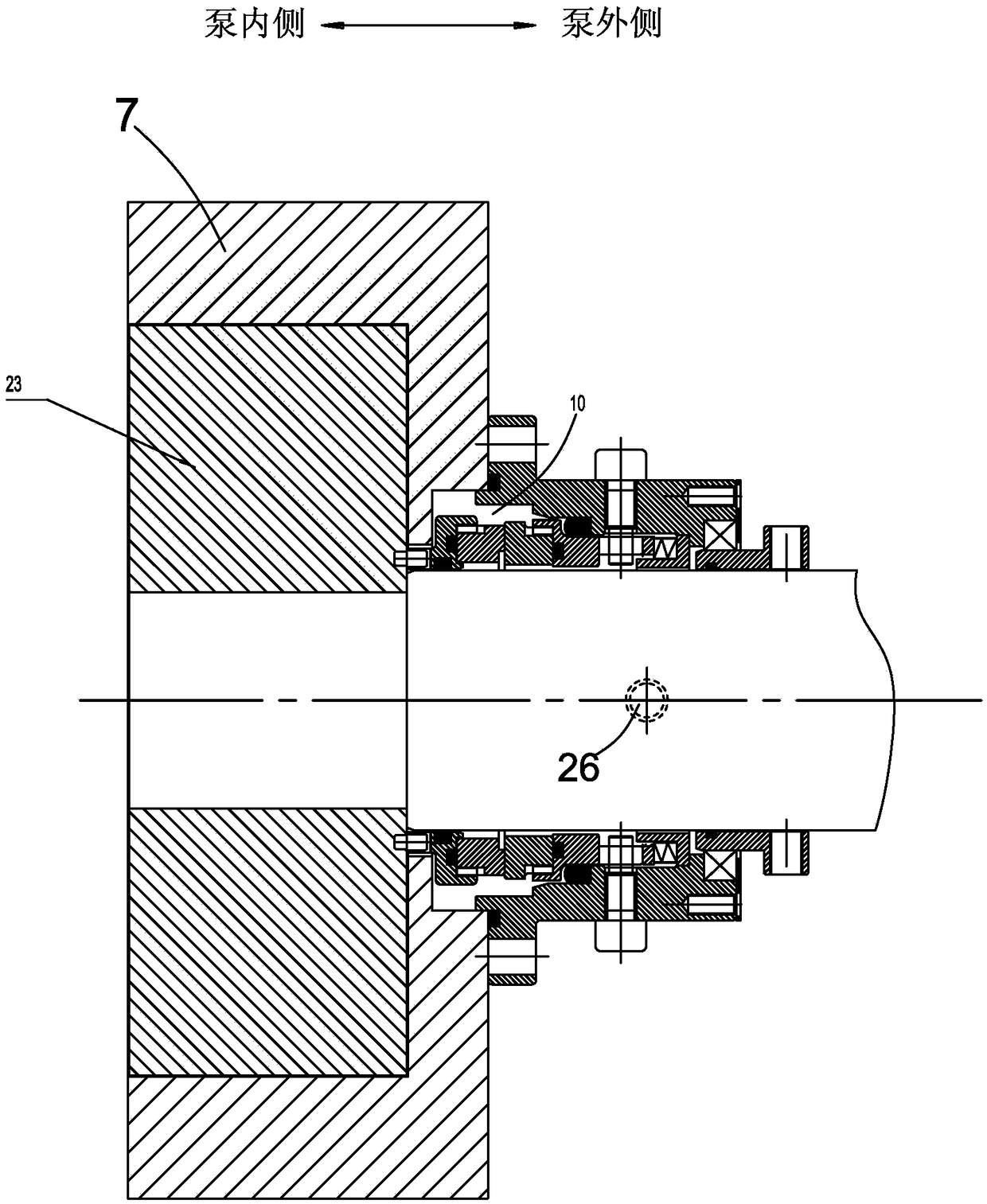
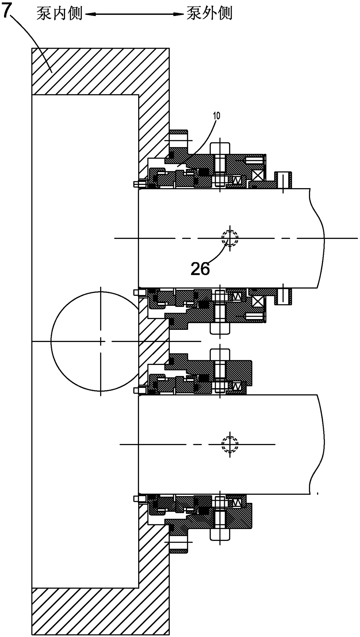
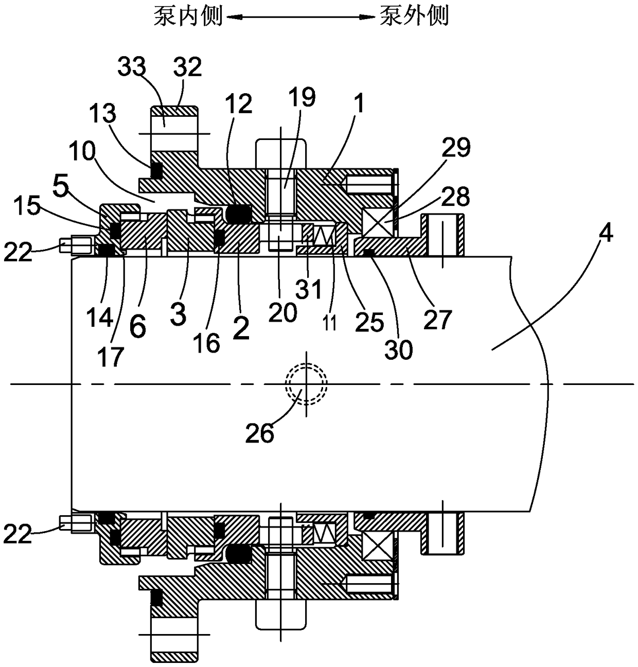
[0044] A rotary lobe pump, such as figure 1 , figure 2 As shown, the shaft 1 of the rotor pump is fixedly connected with the impeller 2 as the rotor, and the two impellers (23) as the interactive rotors are located in the pump body (7), and the two parallel shafts (4) output through the synchronous box are respectively connected with the The corresponding impeller (23) is fixedly connected. The shaft seal of the rotary pump, such as image 3 As shown, it includes the machine seal seat (1), the static ring seat (2), the static ring (3), the moving ring seat (5) rotating with the shaft (4) and the moving ring (6) driven by it, all set outside the shaft (4). Mechanical seal such as Figure 4 , Figure 5 As shown, the static ring seat is as Figure 10 , Figure 11 As shown, the static ring is as Figure 12 , Figure 13 As shown, the moving ring seat is as Image 6 , Figure 7 As shown, the moving ring is as Figure 8 , Figure 9 shown. The mechanical seal seat (1) i...

Embodiment 2

[0053] Such as Figure 18 As shown, the difference between the second embodiment and the first embodiment is that there is no cooling liquid circulation system outside the mechanical seal seat (1). In this way, the circumferential wall of the machine seal seat (1) does not need to offer a cooling liquid inlet and outlet hole (26), nor does it need to arrange a cooling liquid anti-leakage mechanism. Others follow the scheme of Embodiment 1. When the shaft sealing device of the rotor pump in the second embodiment is assembled, the relevant parts of the shaft sealing device can be directly installed on the outside of the pump body (7) in sequence.

Embodiment 3

[0055] Such as Figure 19 As shown, the difference between the third embodiment and the first embodiment is that the material section and the sealing section of the machine seal seat (1) are separately set as the machine seal front seat (1A) and the machine seal rear seat (1B), and the machine seal seat (1) 1) It is an assembly composed of the front seat of the machine seal (1A) and the back seat of the machine seal (1B). The flange end (32) is arranged on the inner side of the pump of the front seat of the machine seal (1A), and along the circumference of the flange end (32) A plurality of connection holes (33) are provided, and the inner cavity of the pump body (7) is provided with a flange installation cavity, and the flange end (32) of the front seat of the mechanical seal (1A) is embedded in the flange installation cavity, and the inner cavity of the pump body (7) The cavity is fixedly connected to the machine seal seat (1) and the pump body (7) via multiple bolts; the se...


PUM


Abstract

The invention provides a rotor pump shaft sealing device which comprising a machine sealing seat (1), a static ring seat (2), a static ring (3), a moving ring seat (5) and a moving ring (6), wherein corresponding sags (9) are formed in the static ring; element rests (8) are arranged on the moving ring seat (5); the corresponding sags (9) are formed in the moving ring (6); the moving ring seat (5),the moving ring (6), the static ring (3) and the static ring seat (2) are sequentially arranged in a material section of an inner cavity of the machine sealing seat (1) along an axis (4) from the inside of a pump to the outside of the pump in a fit manner; an annular cavity (10) for allowing material to enter is formed between the machine sealing seat (1) and the moving ring (6) as well as the static ring (3); a compression spring (11) is arranged in a sealing section of the inner cavity of the machine sealing seat (1); the sags (9) of the moving ring (6) and the static ring (3) are only formed in a part of the thickness of the moving ring (6) and the static ring (3), and the thickness of the remaining parts of the moving ring (6) and the static ring (3) is maintained in an original ringshape; and contact faces of the moving ring (6) and the static ring (3) are closely adhered to each other. The shock strength of the moving ring and the static ring is greatly enhanced, and a phenomenon of cracking of a friction pair can be effectively avoided.

Description

technical field [0001] The invention relates to a rotor pump shaft sealing device. Background technique [0002] Rotor pumps are also called colloid pumps, impeller pumps, universal delivery pumps, etc. Because their impellers are shaped like cams, they are also called cam pumps. Rotor pumps are positive displacement pumps; they are generally double rotors. The rotor pump achieves the purpose of conveying fluid materials by means of the periodic conversion of multiple fixed volume delivery units in the working chamber. Usually, a pair of synchronous gears are driven by a motor to drive the main and auxiliary shafts, and the double rotors are driven by the main and auxiliary shafts to rotate synchronously and in opposite directions, so that the volume of the pump changes, thereby forming a higher vacuum degree and discharge pressure; inlet It is a low-pressure area, and the outlet is a high-pressure area. The rotary lobe pump is mainly used for the transportation of sanitar...

Claims


Application Information

Patent Timeline
IPC IPC(8): F04C15/00
CPCF04C15/00F04C15/0003F04C15/0096
Inventor 谭在良
Owner 浙江华泰邦威泵业有限公司
Learn More