
Backplate manufacturing method and backplate

A manufacturing method and backplane technology, which are applied in manufacturing tools, ion implantation plating, welding medium, etc., can solve the problems of low strength, poor electrical and thermal conductivity, and the quality of the backplane needs to be improved, so as to improve the quality and improve the welding strength. Effect

Active Publication Date: 2019-02-26
KONFOONG MATERIALS INTERNATIONAL CO LTD
View PDF9 Cites 1 Cited by
  • Summary
  • Abstract
  • Description
  • Claims
  • Application Information

AI Technical Summary

Problems solved by technology

Some backplane materials, such as stainless steel substrates, have higher strength, but poor electrical and thermal conductivity; while other backplane materials, such as copper substrates, have better electrical and thermal conductivity, but lower strength. In order to give full play to the advantages of different materials, you can welding two or more materials to obtain the backplate
[0005] However, the quality of the backplane produced by the prior art needs to be improved

Method used


Image

  • Backplate manufacturing method and backplate
  • Backplate manufacturing method and backplate
  • Backplate manufacturing method and backplate

Examples


Embodiment Construction

[0042] It can be seen from the background art that the quality of the backplane manufactured in the prior art needs to be improved.

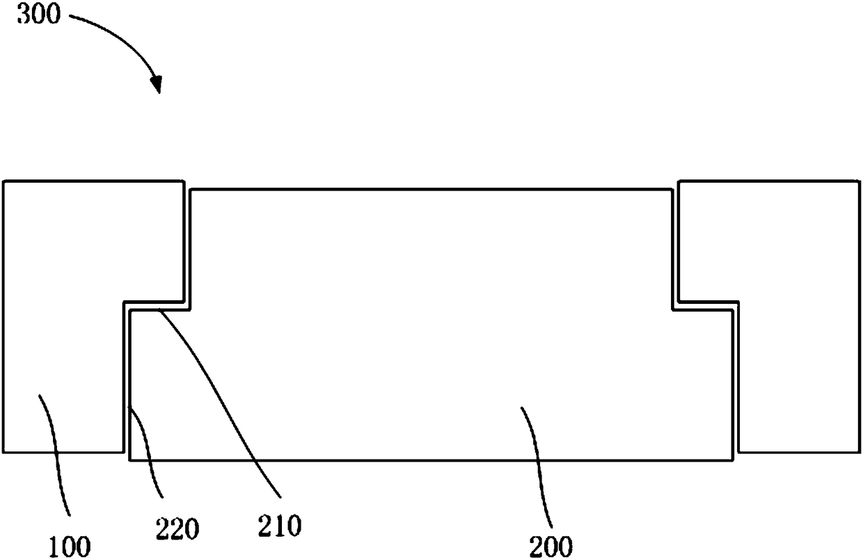
[0043] Now combine with a backplane manufacturing method for analysis. refer to figure 1 , figure 1 It is a schematic diagram of a manufacturing method of a backplane. The stainless steel substrate 100 has a cavity that penetrates up and down. On a section perpendicular to the top surface of the stainless steel substrate 100, the edge of the cavity is stepped; the copper substrate 200 is in the cavity In vivo, the sides of the copper substrate 200 match the cavity. The side of the copper substrate 200 includes a transverse surface 210 and a longitudinal surface 220 , and there is a gap between the longitudinal surface 220 and the cavity, so as to avoid mutual extrusion of the copper substrate 200 and the stainless steel substrate 100 caused by thermal expansion and contraction. During soldering, solder is placed on the lateral surface 210, th...


PUM


Abstract

Provided are a backplate manufacturing method and a backplate. The backplate manufacturing method comprises the steps of providing a first substrate and a second substrate, wherein the top of the first substrate is provided with a groove, the bottom of the second substrate is provided with a convex part, and the convex part is matched with the groove; placing a solder at the bottom of the groove;assembling the first substrate and the second substrate to make the convex part embedded in the groove; melting the solder and welding the first substrate and the second substrate to form the backplate. Because of the obstruction of the groove, the solder can still remain in the groove after being heated and melted and is unlikely to be lost, and therefore the welding quality of the backplate is improved.

Description

technical field [0001] The invention relates to the technical field of semiconductor manufacturing, in particular to a backplane manufacturing method and the backplane. Background technique [0002] Sputtering coating belongs to one of the processes of preparing thin films by physical vapor deposition, specifically refers to the use of high-energy particles to bombard the surface of the sputtering target component, so that the atoms or molecules of the sputtering target component obtain enough energy to escape and deposit Form a thin film on the surface of the substrate or workpiece. [0003] The sputtering target assembly includes a target and a back plate, and the target is fixedly connected to the back plate and assembled together on a sputtering base. The target material is a target material bombarded by high-energy particles, and the back plate is used to fix and support the target material. In addition, the back plate can also conduct electricity and heat. [0004] I...

Claims


Application Information

Patent Timeline
IPC IPC(8): B23K1/00B23K35/30C23C14/34C22C5/08
CPCB23K1/00B23K35/3006C22C5/08C23C14/3407
Inventor 姚力军潘杰相原俊夫王学泽罗明浩陈雪
Owner KONFOONG MATERIALS INTERNATIONAL CO LTD
Learn More