
Electric pile end plate with gas pressure buffering and dehumidifying functions

A technology of gas pressure and gas-electric stacks, applied in circuits, fuel cells, electrical components, etc., can solve the problems of low power density, small volume specific power density, and poor integration, so as to reduce quantity and production costs and increase volume power Density, the effect of accelerating the pace of marketization

Pending Publication Date: 2019-02-22
江苏氢电新能源有限公司
View PDF0 Cites 2 Cited by
  • Summary
  • Abstract
  • Description
  • Claims
  • Application Information

AI Technical Summary

Problems solved by technology

[0004] Disadvantages of the current fuel cell system solutions: 1. Humidifiers and gas buffer tank accessories are expensive, which is one of the main reasons for the high cost of fuel cell systems; 2. Existing commercial humidifiers and gas buffer tanks Strange shape and poor integration with other accessories are not conducive to the miniaturization and compactness of the entire fuel cell system; 3. Commercial humidifiers and gas buffer tanks are large in size, which is one of the main reasons for the large volume and low power density of the fuel cell system
In general, due to the large number of accessories and complex shapes, the fuel cell system is large in size and low in volume specific power density, which limits the promotion and application of fuel cells in the field of vehicles.

Method used


Image

  • Electric pile end plate with gas pressure buffering and dehumidifying functions
  • Electric pile end plate with gas pressure buffering and dehumidifying functions
  • Electric pile end plate with gas pressure buffering and dehumidifying functions

Examples


Embodiment

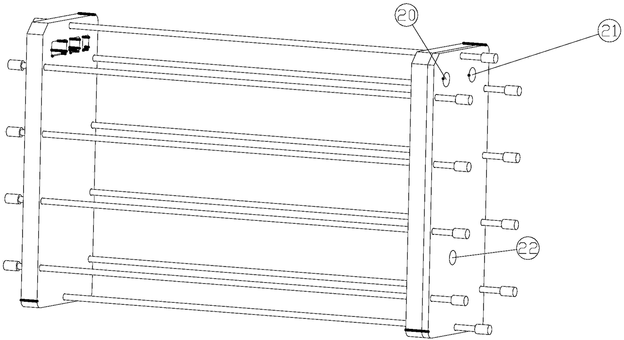
[0024] Embodiment: A cell stack end plate with gas pressure buffering and humidification functions, comprising a first end plate located at the stack gas inlet side and a second end plate located at the cell stack gas outlet side. Both the first end plate and the second end plate are hollow structures.

[0025] The inner cavity of the first end plate is divided into two parts: a fuel gas side intake buffer zone 9 and an oxidant gas side intake buffer zone 10 . The inner cavity of the second end plate is divided into two parts, the tail gas buffer zone 14 on the fuel gas side and the tail gas buffer zone 13 on the oxidant gas side, by the separator. Each buffer zone is provided with a fuel gas side intake buffer adjustment ridge 11 , an oxidant gas side intake buffer adjustment ridge 12 , a fuel gas side exhaust gas buffer adjustment ridge 18 and an oxidant gas side exhaust gas buffer adjustment ridge 19 . Each regulating ridge is shaped in accordance with hydrodynamics, and t...


PUM


Abstract

The invention discloses an electric pile end plate with gas pressure buffering and dehumidifying functions. A first end plate is of a hollow structure, and an inner cavity of the first end plate is partitioned into a fuel gas side gas-inlet buffering area and an oxidant gas side gas-inlet buffering area by a partition plate; and a fuel gas side humidifying water supplementing opening and an oxidant gas side humidifying water supplementing opening are further formed in the side walls of the fuel gas side gas-inlet buffering area and the oxidant gas side gas-inlet buffering area correspondinglyand used for filling the fuel gas side gas-inlet buffering area and the oxidant gas side gas-inlet buffering area with humidifying water correspondingly, the heights of the water levels of the humidifying water on the two sides are larger than the height of a fuel gas end plate inlet and the height of an oxidant gas end plate inlet correspondingly. The electric pile end plate has the gas pressurebuffering and dehumidifying functions, the humidity of gas entering an electric pile is adjusted and changed through design of the buffer areas and the humidifying water temperature, the performanceof the electric pile is exerted advantageously, the service life of the electric pile is prolonged advantageously, and thus the electric pile operates more stably and is longer in service life.

Description

technical field [0001] The invention belongs to the technical field of fuel cells, and in particular relates to an end plate of a fuel cell stack. Background technique [0002] The fuel cell is a device that converts the chemical energy of hydrogen into electrical energy. Its advantages are that the product is water, zero emission and no pollution, low noise, and high conversion efficiency. The working temperature can operate in low temperature environment, it is the first choice for mobile power supply, base station power supply and fixed power supply. A fuel cell is composed of membrane electrodes, bipolar plates, collector plates, end plates and fasteners. [0003] Due to the low voltage of a single polymer membrane fuel cell, in practical applications, multiple battery cells are stacked together and connected in series to form a stack. The current fuel cell system for fuel vehicles is basically composed of a fuel cell stack, a humidifier, a gas buffer tank, a starting ...

Claims


Application Information

Patent Timeline
Patent Type & Authority Applications(China)
IPC IPC(8): H01M8/04082H01M8/04089H01M8/04119H01M8/04746H01M8/04828H01M8/2457H01M8/2475H01M8/2483
CPCH01M8/04104H01M8/04126H01M8/04201H01M8/04753H01M8/04835H01M8/2457H01M8/2475H01M8/2483Y02E60/50
Inventor 魏广科王习鹏石奎孔明程立明
Owner 江苏氢电新能源有限公司
Learn More