LED automobile lamp

A technology for LED car lights and LED light panels, which is applied in the direction of headlights, motor vehicles, road vehicles, etc., can solve the problems of low aluminum alloy thickness and thermal conductivity, mirror shrinkage, and local thickness of the mirror, so as to save the installation process. , the effect of simplifying the structure and improving the assembly efficiency

Pending Publication Date: 2019-02-22
CARICAN UOG OPTICS SUZHOU CO LTD
View PDF0 Cites 0 Cited by
  • Summary
  • Abstract
  • Description
  • Claims
  • Application Information

AI Technical Summary

Problems solved by technology

[0003] However, ordinary LED car headlights use profiled aluminum alloy as the main body of heat conduction. Since the distance between the center point of the light source is required to be as small as possible for car headlights, the thickness of the aluminum alloy material as the main body should not be too thick, and the heat conduction of aluminum alloy The coefficient is only 200w / m·k. In practical applications, due to the low thickness and thermal conductivity of the aluminum alloy in contact with the light source, the temperature difference between the light source and the radiator is large, and the temperature difference is generally 40-70°C, which cannot be well The heat is exported, thereby affecting the use effect and service life of LED lights, and the following obvious defects generally exist:
[0004] 1. The installation of the reflector itself and the installation of the LED circuit board on the reflector are generally connected by screws. Correspondingly, a screw column structure needs to be set on the back of the reflector, resulting in a thicker part of the reflector, which is very easy to make the reflector when injection molding. produce miniatures on the front side;
[0005] 2. Since the circuit board cannot be bent multiple times, it is difficult to meet the complex shape requirements

Method used


Image

  • LED automobile lamp
  • LED automobile lamp

Examples


Embodiment Construction

[0023] In order to make the purpose, technical solutions and advantages of the present invention clearer, the technical solutions in the embodiments of the present invention will be clearly and completely described below in conjunction with the accompanying drawings in the embodiments of the present invention. Obviously, the described embodiments are only Some, but not all, embodiments of the invention. Based on the embodiments of the present invention, all other embodiments obtained by persons of ordinary skill in the art without making creative efforts belong to the protection scope of the present invention.

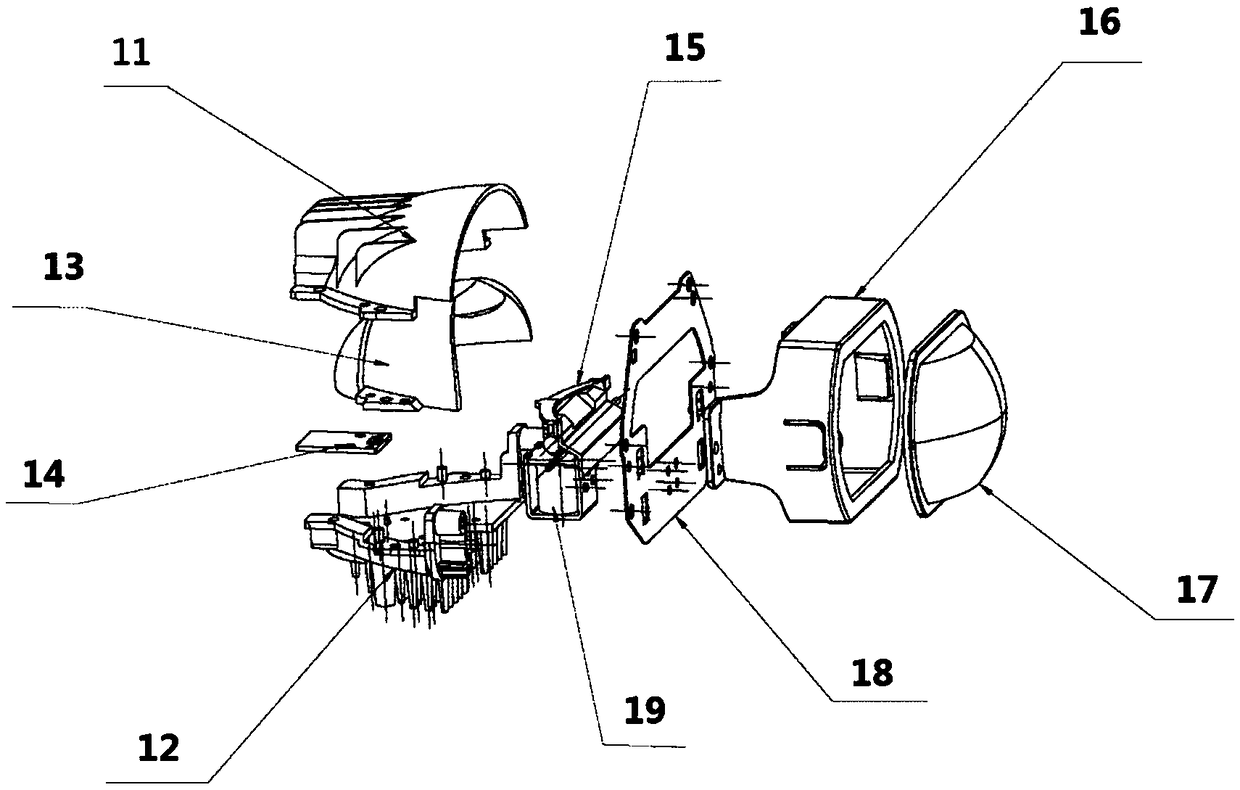
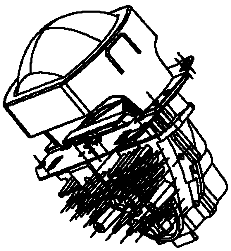
[0024] refer to figure 1 , figure 2 As shown, a kind of LED automobile light, comprises upper radiator 11, lower radiator 12, fan, reflector 13, LED lamp board 14, shading baffle 15, specifically, lower radiator 12 is arranged on the upper radiator 11 The lower part and the upper radiator 11 are connected together by screws or rivets, the reflector 13 is arranged cl...


PUM


Abstract

The invention belongs to the technical field of LED lamps, and discloses an LED automobile lamp. The LED automobile lamp comprises an upper radiator, a lower radiator which is arranged below the upperradiator and connected with the upper radiator, a reflecting mirror which is arranged under the upper radiator and connected with the upper radiator, and an LED lamp panel which is arranged between the reflecting mirror and the lower radiator and fixed by the upper radiator and the lower radiator. According to the technical scheme, the upper portion and the lower portion of a light source of theLED lamp are subjected to heat dissipation by the upper radiator and the lower radiator at the same time, the problem that the LED automobile lamp is poor in heat dissipation is effectively solved, meanwhile, the LED lamp panel of the technical scheme is directly clamped and fixed between the upper radiator and the lower radiator, thus, the structure of the LED automobile lamp can be simplified, other installation procedures are omitted, and the assembling efficiency of the LED automobile lamp is effectively improved.

Description

technical field [0001] The invention relates to the technical field of LED lamps, in particular to an LED automobile lamp. Background technique [0002] There are two kinds of light sources for traditional car lights and headlights: halogen lamps and xenon lamps. The photoelectric conversion rate of halogen lamps is not high, which consumes electricity, has insufficient brightness, and has a short life. Install a high-voltage package to boost the voltage by 15-25KV, and the working temperature of the bulb is >350°C, so there are certain potential safety hazards. With the development of lighting technology, LED lamps have quickly replaced traditional lamps and become the most widely used modern lighting tools in the world due to their advantages such as low power consumption, long life, high brightness, low heat, and environmental protection. Now, LED lights have been widely used in the automotive industry, and various LED car lights emerge in endlessly on the market. ...

Claims


Application Information

Patent Timeline
IPC IPC(8): F21S41/32F21S45/47F21V29/503F21V29/70F21W102/10F21W107/10F21Y115/10
CPCF21S41/32F21S45/47F21V29/503F21V29/70F21W2102/10F21Y2115/10F21W2107/10
Inventor 林资凯顾炜
Owner CARICAN UOG OPTICS SUZHOU CO LTD
Why Eureka
Try Eureka