
Novel steel plate beam and steel-concrete bond beam

A new type of steel plate beam technology, applied in the direction of load-bearing elongated structural members, girders, joists, etc., can solve problems such as difficulty in guaranteeing the deformation degree of welded steel plate beams, affecting the safety of bridge structures, and weak structural stress. , to achieve the effect of easy guarantee of welding quality, solving welding quality problems, and convenient processing and production.

Pending Publication Date: 2019-02-22
CHINA RAILWAY ERYUAN ENG GRP CO LTD
View PDF7 Cites 1 Cited by
  • Summary
  • Abstract
  • Description
  • Claims
  • Application Information

AI Technical Summary

Problems solved by technology

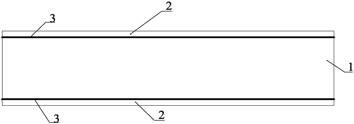
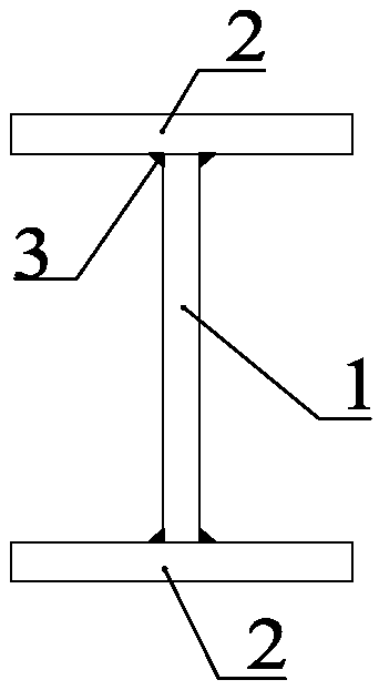
like Figure 1-Figure 2 As shown, the steel plate girder with a beam height of 1.2m or more is formed by welding two flange plates 2 to the web 1 respectively. Such a steel plate girder includes four fillet weld structures, although the welding method can meet Beam height requirements, but a large number of fillet welds 3 not only have high welding strength, but also the welding quality and the degree of deformation of the steel plate girder are difficult to guarantee. The fillet welds 3 become the weak area of ​​the structure. seriously affect the safety of the bridge structure

Method used


Image

  • Novel steel plate beam and steel-concrete bond beam
  • Novel steel plate beam and steel-concrete bond beam
  • Novel steel plate beam and steel-concrete bond beam

Examples


Embodiment 1

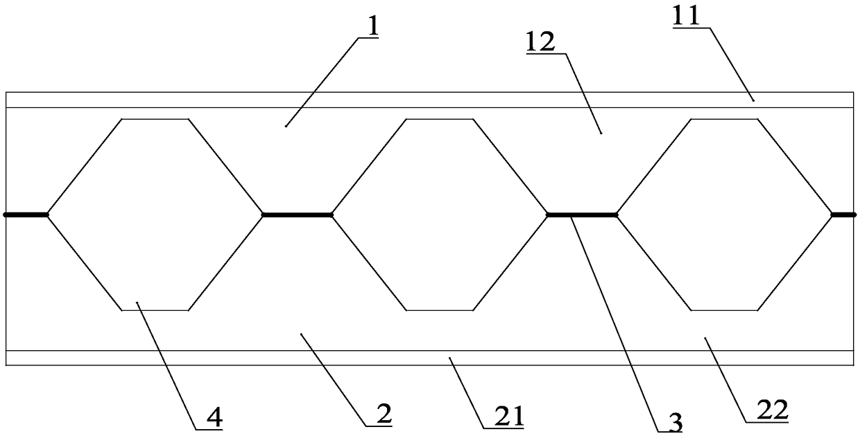
[0045] Such as Figure 3-Figure 8 As shown, a new type of steel plate girder includes a first assembled part 1 and a second assembled part 2, the first assembled part 1 includes a flange plate 11 and a web plate 12 integrally rolled and formed, and the first assembled part 1 The second assembling part 2 includes the flange plate 2 21 and the web 2 22 integrally rolled, and the web 12 and the web 2 22 are connected by a butt weld 3, and the butt weld 3 is fully melted Penetrating butt welds. Several hexagonal cavities 4 are formed between the first web 12 and the second web 22, and the cavities 4 are axisymmetric structures. Specifically, the side of the web one 12 away from the flange plate 11 is cut off by several cavity units 1 41, and the side of the web two 22 away from the flange plate two 21 is also cut off by several The second cavity unit 42 is cut off, and the openings of the first cavity unit 41 and the second cavity unit 42 are adapted to form the cavity 4 .

[0...

Embodiment 2

[0053] Such as Figure 11-Figure 12 As shown, a steel-concrete combined beam includes any one of the novel steel plate girders, and a concrete slab 6 covered on the new steel plate girder, and the new steel plate girder and the concrete slab 6 Connectors 7 are connected between them, thereby forming an integral structure that bears force together. The connecting piece 7 may be a shear nail or the like. At this time, not only the girder height of the new steel plate girder has been greatly increased to meet the construction requirements, but also the quality problem of the fillet welds has been solved. If the concrete slab is covered on it, the high tensile strength of the steel material, good ductility and concrete resistance will be fully utilized. The advantages of high compressive strength and high rigidity are very suitable for the field of bridge engineering.

Embodiment 3

[0055] Such as Figure 13 As shown, the difference between this embodiment and Embodiment 1 is that the distance between the cavity 4 and the first flange plate 11 is equal to the distance between the cavity 4 and the second flange plate 21, that is, when cutting, the The distance between the high cutting line 52 and the first flange plate 11 is equal to the distance between the low cutting line 53 and the second flange plate 21 , ie D1 = D2 . The size and shape of the first assembling part 1 and the second assembling part 2 formed by cutting in this way are convenient for assembling and processing.

[0056] When the girder height of the integrally rolled steel plate girder 1 is 1.2m, the processing method of the present invention can not only process a steel plate girder with a girder height greater than 1.2m, but can even process a steel plate with a girder height greater than or equal to 2m beam. In this embodiment, the beam height of the integrally rolled steel plate gir...


PUM


Abstract

The invention discloses a novel steel plate beam and a steel-concrete bond beam. The novel steel plate beam comprises a first splicing part and a second splicing part. The first splicing part comprises a frange plate I and a web plate II which are integrally rolled and formed; the second splicing part comprises a frange plate II and a web plate II which are integrally rolled and formed, and the web plate I and the web plate II are connected by means of a butt weld. The steel-concrete bond beam comprises any one novel steel plate beam and a concrete plate covering the novel steel plate beam. Aconnecting part is connected between the novel steel plate beam and the concrete plate. The novel steel plate beam is formed by splicing the first splicing part and the second splicing part, so that the height of the steel plate beam can be improved greatly. The first splicing part and the second splicing part are rolled and formed, and the web plates and the frange plates are connected tightly, so that no fillet welds are available and the force transfer property is excellent. Furthermore, the first splicing part and the second splicing part are connected through the butt weld, so that the novel steel plate beam is convenient to process and manufacture, and the welding quality of the butt weld is easily guaranteed.

Description

technical field [0001] The invention relates to the technical field of bridge engineering, in particular to a novel steel plate beam and a steel-concrete combined beam. Background technique [0002] Steel-concrete composite beams can give full play to the advantages of high tensile strength and ductility of steel and high compressive strength and rigidity of concrete, and are more and more widely used in bridge engineering. Most of the steel-concrete combined beams use I-shaped steel plate girders, especially for medium and long-span bridges, which have high requirements for the stiffness and bending resistance of the main girder, and the height of the main girder, that is, the design height of the steel girder, will be greater than However, under the existing processing technology, only steel plate girders with a girder height below 1.2m can be obtained by integral rolling. Such as Figure 1-Figure 2 As shown, steel plate girders with a beam height of 1.2m or more are form...

Claims


Application Information

Patent Timeline
IPC IPC(8): E04C3/04E04C3/293E04C3/08
CPCE04C3/04E04C3/083E04C3/293E04C2003/0413E04C2003/043
Inventor 曾永平陈克坚徐昕宇陶奇陈星宇郑晓龙杨国静苏延文董俊庞林周川江颜永逸刘力维
Owner CHINA RAILWAY ERYUAN ENG GRP CO LTD
Learn More