
Debris flow prevention and treatment device and method

A technology for debris flow and debris flow ditch, which is applied in the field of debris flow prevention, debris flow prevention and control devices, and prevention and control devices, can solve problems such as inability to divert, reduce performance, harm, etc., and achieve the effects of increasing stability, improving strength, and early protection.

Inactive Publication Date: 2019-02-22
浙江杭博生态环境建设有限公司
View PDF7 Cites 4 Cited by
  • Summary
  • Abstract
  • Description
  • Claims
  • Application Information

AI Technical Summary

Problems solved by technology

[0003] Debris flow is an extremely harmful geological disaster. China has a large area of ​​mountains and steep terrain. Concentrated rainfall can easily cause debris flow. The basin of a typical debris flow generally includes the formation area, circulation area, and accumulation area. Debris flow prevention and control projects are generally set in the formation area Or the circulation area, it is usually necessary to protect it with some structural devices to reduce the degree of damage, but the existing prevention and control devices have certain disadvantages in use, and the protection devices for it can only block larger solid objects when they occur. The whereabouts of it cannot be diverted. When the large and small materials are piled up together, it will generate a greater momentum, causing harm to the lower side and reducing its performance.

Method used


Image

  • Debris flow prevention and treatment device and method
  • Debris flow prevention and treatment device and method
  • Debris flow prevention and treatment device and method

Examples


Embodiment Construction

[0025] The following will clearly and completely describe the technical solutions in the embodiments of the present invention with reference to the accompanying drawings in the embodiments of the present invention. Obviously, the described embodiments are only some, not all, embodiments of the present invention. Based on the embodiments of the present invention, all other embodiments obtained by persons of ordinary skill in the art without making creative efforts belong to the protection scope of the present invention.

[0026] In the description of the present invention, it should be noted that the terms "upper", "lower", "inner", "outer", "front end", "rear end", "both ends", "one end", "another end" The orientation or positional relationship indicated by etc. is based on the orientation or positional relationship shown in the drawings, and is only for the convenience of describing the present invention and simplifying the description, rather than indicating or implying that ...


PUM


Abstract

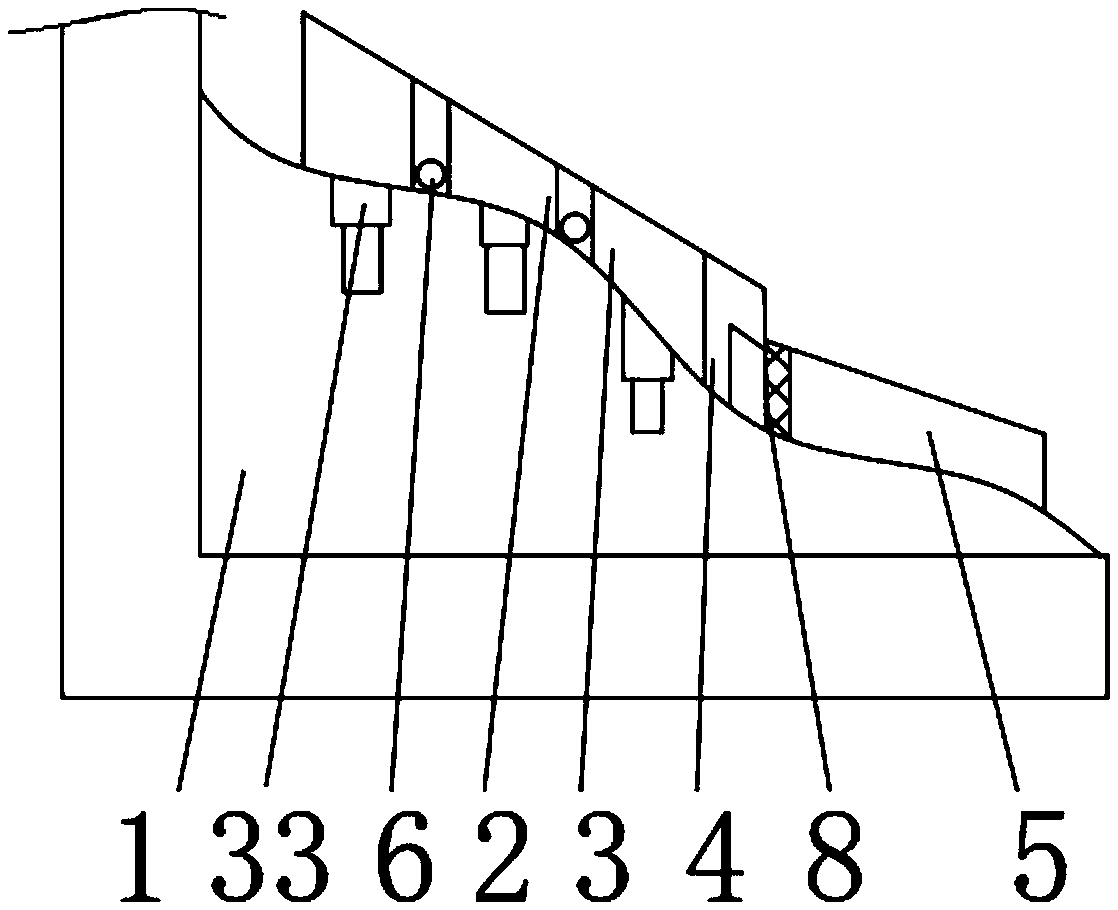
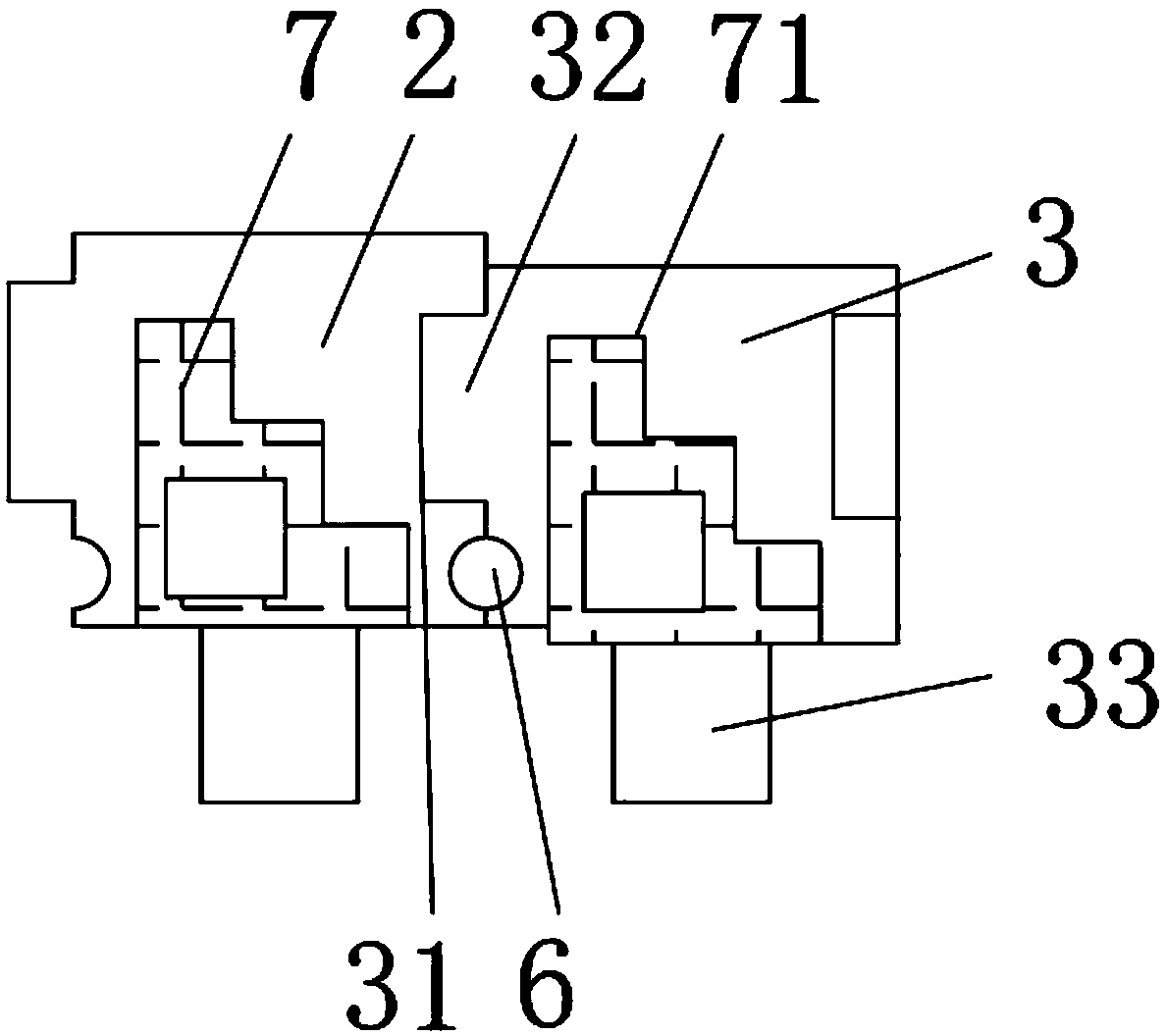
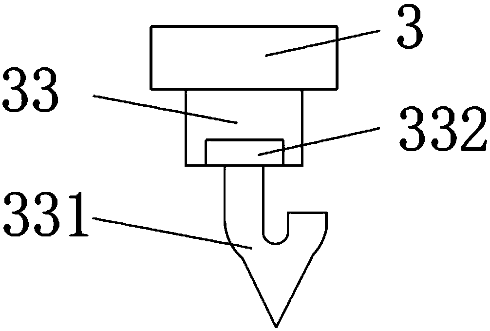
The invention discloses a debris flow prevention and treatment device and method. A debris flow ditch is included, the outer surface of the upper end of the debris flow ditch is provided with first intercepting dams and second intercepting dams, the first intercepting dams are located on one sides of the second intercepting dams, a water flowing groove is formed between the two first interceptingdams in a longitudinal connection manner, and a first baffle is arranged between the two first intercepting dams in a transverse connection manner. The method comprises the following steps that firstly, related situations of the debris flow ditch are investigated and analyzed; secondly, the field area of the debris flow ditch is subjected to the statistics, and the development tendency of the debris flow ditch is predicted; thirdly, the intercepting and dredging project is set; and fourthly, the scour prevention forest is arranged. Mainly for the debris flow prevention and treatment device andmethod, components in the debris flow can be effectively subjected to flow dividing, the flow swashing speed of the debris flow can be reduced, large-solid landslide can be effectively hindered, thedownward flow activity of gravels and liquid is not hindered, the situation that the solid is left and liquid flows away is achieved, in addition, the strength of soil is improved, and the loose solidobject source is reduced.

Description

technical field [0001] The invention relates to the field of prevention and control devices, in particular to a debris flow prevention and control device. [0002] The invention relates to the field of prevention and control methods, in particular to a mud-rock flow prevention and control method. Background technique [0003] Debris flow is an extremely harmful geological disaster. China has a large area of ​​mountains and steep terrain. Concentrated rainfall can easily cause debris flow. The basin of a typical debris flow generally includes the formation area, circulation area, and accumulation area. Debris flow prevention and control projects are generally set in the formation area Or the circulation area, it is usually necessary to protect it with some structural devices to reduce the degree of damage, but the existing prevention and control devices have certain disadvantages in use, and the protection devices for it can only block larger solid objects when they occur. T...

Claims


Application Information

Patent Timeline
Patent Type & Authority Applications(China)
IPC IPC(8): E01F7/04E02B7/02
CPCE01F7/04E02B7/02
Inventor 董雅琴项义虎冯波娜
Owner 浙江杭博生态环境建设有限公司
Learn More