
Equipment cabin pultrusion technology

A pultrusion process and equipment cabin technology, applied in the field of rail transit, can solve the problems of low fiber content, achieve the effects of reducing quality, ensuring manufacturability, and enhancing saturation

Inactive Publication Date: 2019-02-22
NEWTRY COMPOSITE
View PDF4 Cites 13 Cited by
  • Summary
  • Abstract
  • Description
  • Claims
  • Application Information

AI Technical Summary

Problems solved by technology

[0007] In view of this, the present invention proposes a pultrusion process for equipment cabins, aiming to solve the technical problem of low fiber content in the production of carbon fiber equipment cabins by traditional vacuum infusion, molding or RTM processes in the prior art

Method used

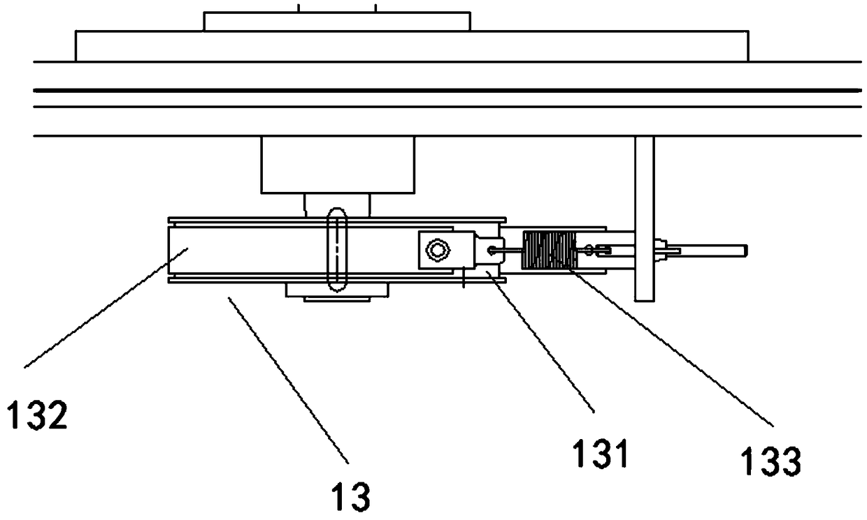

Image

  • Equipment cabin pultrusion technology
  • Equipment cabin pultrusion technology
  • Equipment cabin pultrusion technology

Examples


Embodiment Construction

[0029] Exemplary embodiments of the present disclosure will be described in more detail below with reference to the accompanying drawings. Although exemplary embodiments of the present disclosure are shown in the drawings, it should be understood that the present disclosure may be embodied in various forms and should not be limited by the embodiments set forth herein. Rather, these embodiments are provided for more thorough understanding of the present disclosure and to fully convey the scope of the present disclosure to those skilled in the art. It should be noted that, in the case of no conflict, the embodiments of the present invention and the features in the embodiments can be combined with each other. The present invention will be described in detail below with reference to the accompanying drawings and examples.

[0030] refer to figure 1 , it can be seen from the figure that the equipment cabin pultrusion process proposed by the embodiment of the present invention inc...


PUM


Abstract

The invention provides an equipment cabin pultrusion technology. The equipment cabin pultrusion technology comprises the steps that firstly, fiber yarn and fiber fabric are discharged at the same time, an equipment cabin body part is made of fiber fabric, and fiber yarn is adopted at the corner part or the thickened part; secondly, a pre-forming die is used for conducting pre-forming treatment onthe fiber yarn and the fiber fabric, the pre-forming die comprises a plurality of pre-forming plates, the pre-forming plates are provided with hollow grooves, the hollow grooves can gradually change,and finally the product shape is formed; thirdly, glue injection type pultrusion is conducted on the pre-formed fiber yarn and the pre-formed fiber fabric; fourthly, a curing die is used for conducting curing on the fiber yarn and the fiber fabric obtained after pultrusion; and fifthly, an automatic cutting machine is used for cutting the cured fiber yarn and the cured fiber fabric. Compared withthe prior art, the fiber fabric and fiber yarn mixed pultrusion manner is adopted, holes of the fiber fabric are filled, the fiber content reaches up to 80%, and the equipment cabin mass is further reduced.

Description

technical field [0001] The invention relates to the technical field of rail transit, in particular to a pultrusion process for an equipment cabin. Background technique [0002] The equipment cabin is a cabin space located at the bottom of the motor car for placing equipment. Its function is to protect the equipment from the collision and interference of foreign objects such as rain, snow, wind and sand. The acceleration and aerodynamic loads received by the train during operation also act on the equipment cabin. Therefore, the overall structural rationality and strength of the equipment compartment play a vital role in the operation safety of the train. [0003] Traditional equipment compartment brackets are mostly made of aluminum alloy or other metal materials, and the assembly method is welding, which has the disadvantages of heavy weight, high energy consumption for welding, labor-intensive, and high cost. Especially with the speed increase of high-speed rail, it has be...

Claims


Application Information

Patent Timeline
IPC IPC(8): B29C70/52B29C70/54
CPCB29C70/52B29C70/525
Inventor 解祥夫谈源王瑞耿强华张军
Owner NEWTRY COMPOSITE
Learn More