
Pipe inner wall positioning and cooling device and method

A cooling device and a technology for the inner wall of the pipe, which is applied in the field of cooling the inner wall of the pipe, can solve problems such as the melting of the oxide scale of the steel pipe, and achieve the effect of preventing cracks

Pending Publication Date: 2019-02-22
江苏宏宝优特管业制造有限公司
View PDF8 Cites 1 Cited by
  • Summary
  • Abstract
  • Description
  • Claims
  • Application Information

AI Technical Summary

Problems solved by technology

[0004] One of the objectives of the present invention is to solve the problem that high-frequency welding in the prior art does not cool the inner surface of the steel pipe, causing cracks and melting of the oxide scale of the steel pipe

Method used


Image

  • Pipe inner wall positioning and cooling device and method
  • Pipe inner wall positioning and cooling device and method
  • Pipe inner wall positioning and cooling device and method

Examples


Embodiment 1

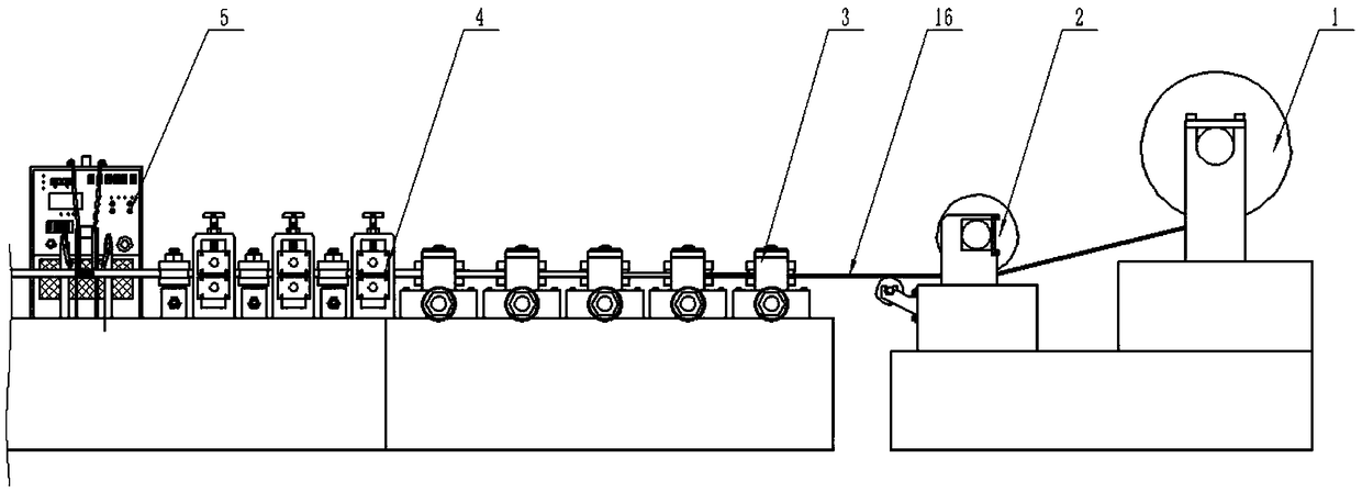
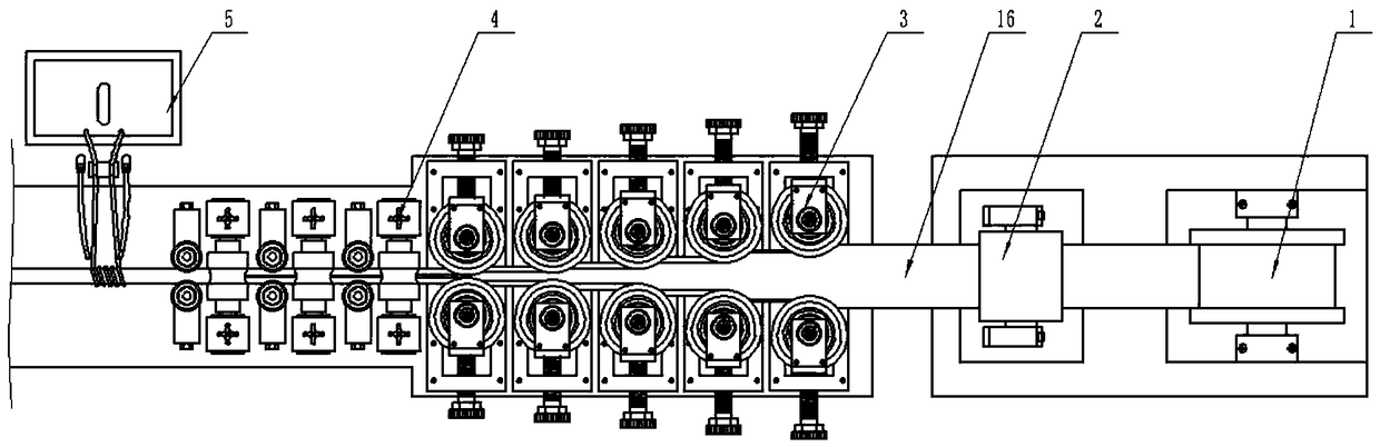
[0058] A tube inner wall positioning cooling device, such as Figure 5 , 6 , 7, 8, and 12, including: liquid supply pipe 10, liquid storage tank 6, infusion pipe 7, water supply pump 8, support 9, self-rotating nozzle 15, temperature sensor 17, thermostat, relay. The lower end of the infusion pipe 7 is connected to the liquid storage tank 6, the water nozzle of the water supply pump 8 is connected to the right end of the infusion pipe 7, and the drain nozzle of the water supply pump 8 is connected to the right end of the liquid supply pipe 10. The water supply pump 8 and the bracket 9 have screws 113. The water supply pump 8 is fixed by rotating the screws 113. The self-rotating nozzle 15 is connected to the left end of the liquid supply pipe 10. The temperature sensor 17 is fixedly connected to the outer surface of the liquid supply pipe 10. The temperature sensor 17 is close to the self-rotating nozzle. 15, located at the right end of the self-rotating nozzle 15, the thermo...

Embodiment 2

[0079] A method for positioning and cooling the inner wall of a tube, comprising the following steps:

[0080] Adjust the thermostat, the thermostat compares the temperature produced when the existing welding device 5 welds the steel pipe to set the temperature, when the signal detected by the temperature sensor 17 indicates that the existing welding device 5 welded steel pipe reaches the set temperature, the thermostat will Connect the relay to make the water supply pump 8 energized;

[0081] Positioning, by sliding the water supply pump 8, further controlling the movement of the liquid supply pipe 10, when the temperature sensor 17 on the liquid supply pipe 10 detects that the welded steel pipe of the existing welding device 5 reaches the set temperature (checked by the thermostat), then the The screw 113 fixes the water supply pump 8 so that the self-rotating nozzle 15 is inside the steel pipe at the welding position;

[0082] Liquid supply, when the temperature sensor 17 ...


PUM


Abstract

The invention discloses a pipe inner wall positioning and cooling device and relates to the technical field of pipe inner wall cooling. The pipe inner wall positioning and cooling device comprises a liquid supply pipe, a liquid storage box, a liquid conveying pipe, a water pump, a bracket, a self-rotation sprayer, a temperature sensor, a temperature controller and a relay. The pipe inner wall positioning and cooling device adopts the temperature sensor to position a thermal-state steel pipe to prevent a steel pipe forming machine tool from reassembling and adjustment when a component is repaired or replaced or prevent the steel pipe forming machine tool from component position adjustment during the cleaning process to avoid reassembling and adjustment, so that the thermal-state steel pipeis cooled. The pipe inner wall positioning and cooling device adopts the self-rotation sprayer to cool the inner wall of the steel pipe, so that the situation that high-frequency welding does not coolthe inner surface of the steel pipe to cause a crack and to melt the oxide scale of the steel pipe is prevented.

Description

technical field [0001] The invention relates to the technical field of pipe inner wall cooling, in particular to a pipe inner wall positioning cooling device. Background technique [0002] In the existing technology, such as figure 1 , 2 As shown, when the steel pipe is formed, the uncoiler 1 is firstly used to feed the steel strip 16, and secondly, the steel strip 16 is leveled by using the steel strip guide device 2, as shown in Figure 4 As shown, the arc chamfer 31 that the vertical mold group 3 and the horizontal mold group 4 all have is utilized to pressurize the narrow direction position of the steel strip 16 afterwards, as image 3 As shown, the narrow edges of the steel strip 16 are forced to bend toward the center. Utilize welding device 5 at last to carry out welding work to the slit of the steel pipe (the slit that the narrow edge of steel strip 16 two ends forms) of the steel pipe produced after the forming of steel strip 16, reaches the purpose of eliminatin...

Claims


Application Information

Patent Timeline
Patent Type & Authority Applications(China)
IPC IPC(8): B23K13/00B23K37/00
CPCB23K13/00B23K37/003
Inventor 王忠华仲蔡希黄玲
Owner 江苏宏宝优特管业制造有限公司
Learn More