Antenna for remote tag identification

A long-distance, tag technology, applied in the field of antennas for long-distance reading of tags, can solve the problems of heavy police burden, limited security inspection methods, and personnel detention.

Pending Publication Date: 2019-02-19
THE FIRST RES INST OF MIN OF PUBLIC SECURITY
View PDF7 Cites 0 Cited by
  • Summary
  • Abstract
  • Description
  • Claims
  • Application Information

AI Technical Summary

Problems solved by technology

However, at present, the security check methods for passengers’ identities in these places are still relatively limited, and the police mainly use ordinary handheld or desktop second-generation resident ID card readers to conduct spot checks on the spot. The main disadvantage of these types of readers is that they can read The short distance and small range lead to problems such as low security inspection efficiency, small proportion of inspection personnel, and heavy burden on the police. Sometimes large-scale personnel are stranded or suspicious personnel are missed.

Method used


Image

  • Antenna for remote tag identification
  • Antenna for remote tag identification
  • Antenna for remote tag identification

Examples


Embodiment 1

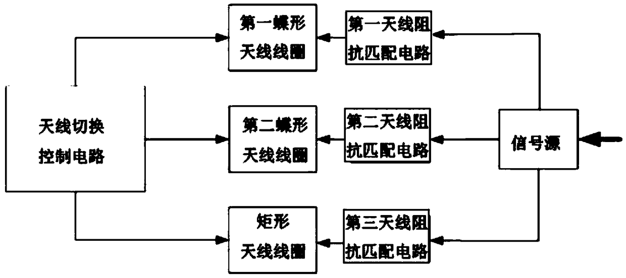
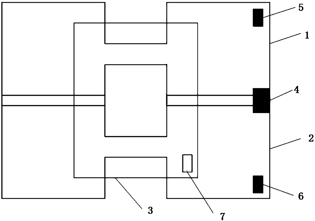
[0022] Such as Figure 1-2 As shown, an antenna for long-distance reading tags includes a first butterfly antenna coil 1, a second butterfly antenna coil 2 and a rectangular antenna coil 3, the first butterfly antenna coil 1 and the second butterfly antenna coil 2 Relatively arranged and partially overlapped, the rectangular antenna coil 3 is located in the middle of the area formed by the first butterfly antenna coil 1 and the second butterfly antenna coil 2; the first butterfly antenna coil 1, the second butterfly antenna coil 2 and the rectangular antenna coil 3 are respectively connected to the signal source through the first antenna impedance matching circuit 5, the second antenna impedance matching circuit 6 and the third antenna impedance matching circuit 7; the first butterfly antenna coil 1, the second butterfly antenna coil The antenna coil 2 and the rectangular antenna coil 3 are all connected to the antenna switching control circuit 4, and the antenna switching con...

Embodiment 2

[0031] Such as Figure 7 As shown, in this embodiment, two antennas 100 for long-distance reading tags described in Embodiment 1 are symmetrically installed on both sides of the passage door consisting of two non-metallic door panels 101 with a distance of 70 cm and a top cabinet 102 .

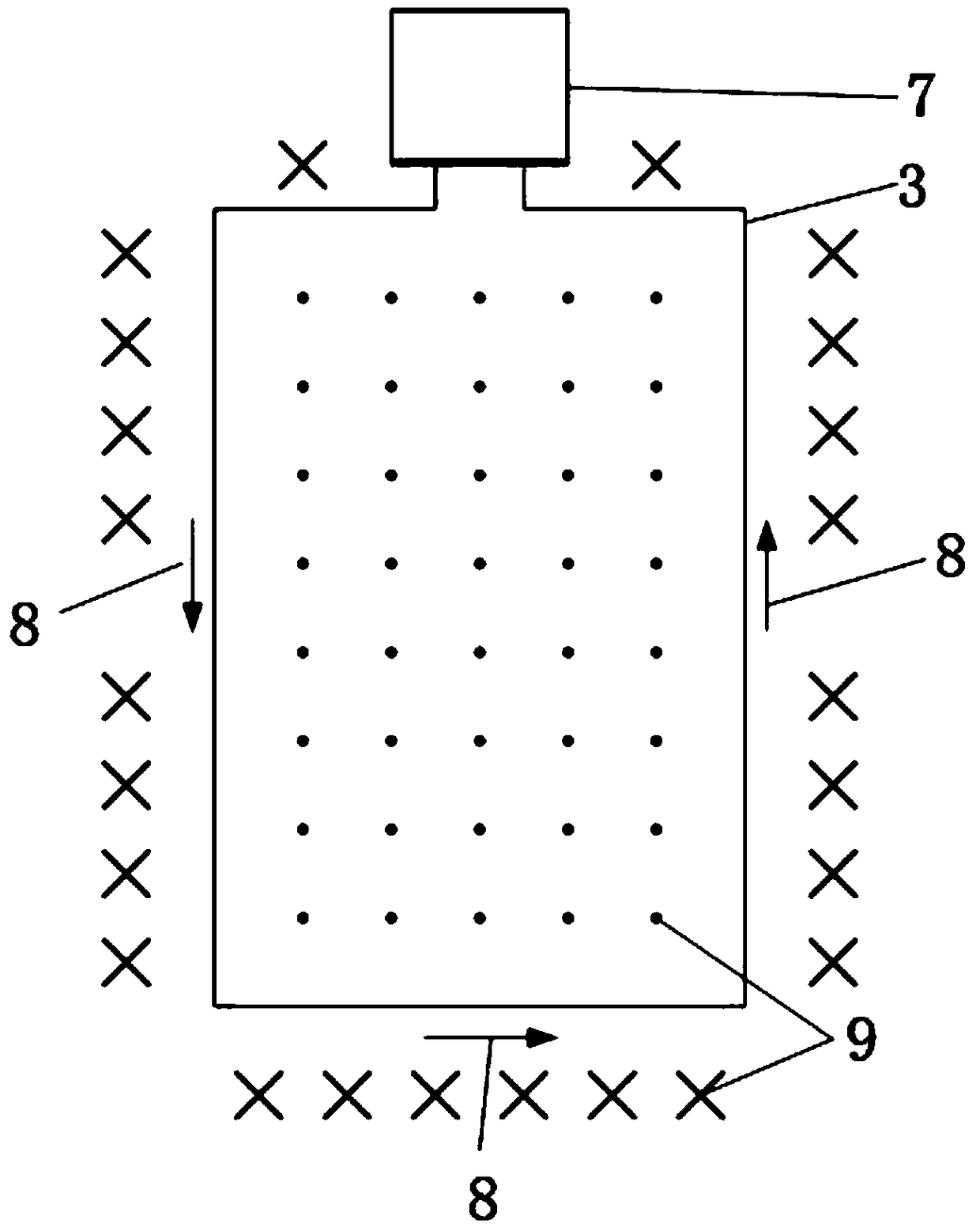
[0032] In order to realize the long-distance reading of the antenna, it is necessary to increase the area of ​​the antenna coil and expand the range of the magnetic field generated by the antenna coil, so that the 13.56MHz RFID tag can still couple enough energy from the magnetic field far away from the metal coil to activate the chip in the card body . For a metal coil loop with radius R, when the number of turns is N, the magnetic field strength at a distance x from the coil is:

[0033]

[0034] Since the magnetic field strength and the coil radius R are not in a linear relationship, in order to mathematically obtain the relationship between the maximum magnetic field strength and the ...


PUM


Abstract

The invention discloses an antenna for remote tag identification. The antenna comprises a first butterfly antenna coil, a second butterfly antenna coil and a rectangular antenna coil. The first butterfly antenna coil, the second butterfly antenna coil and the rectangular antenna coil are connected to a signal source through a first antenna impedance matching circuit, a second antenna impedance matching circuit and a third antenna impedance matching circuit respectively and are all connected to an antenna switching control circuit. The antenna switching control circuit is used for switching among the first butterfly antenna coil, the second butterfly antenna coil and the rectangular antenna coil to enable the first butterfly antenna coil, the second butterfly antenna coil and the rectangular antenna coil to radiate energy to the space in turns. By the antenna, the requirement of remote identification of 13.56MHzRFID tag information can be met, and special application in the field of public security to densely populated places can be realized.

Description

technical field [0001] The invention relates to the field of RFID technology, in particular to an antenna for long-distance reading tags. Background technique [0002] Many violent terrorist incidents in recent years have shown that places with a high density of people, such as subways, buses, and train stations, have become the first choice for terrorist attacks. However, at present, the security check methods for passengers’ identities in these places are still relatively limited, and the police mainly use ordinary handheld or desktop second-generation resident ID card readers to conduct spot checks on the spot. The main disadvantage of these types of readers is that they can read The short distance and small scope have led to problems such as low security inspection efficiency, a small proportion of inspection personnel, and a heavy burden on the police. From time to time, large-scale personnel are stranded or suspicious personnel are missed. Contents of the invention ...

Claims


Application Information

Patent Timeline
Patent Type & Authority Applications(China)
IPC IPC(8): H01Q1/36H01Q3/24H01Q7/00H01Q21/29H01Q1/22G06K19/077
CPCH01Q1/2216H01Q1/36H01Q3/247H01Q7/00H01Q21/29G06K19/07749G06K19/07773
Inventor 高彬李刚李胜广谭林陈毓赵士伟冉旭阳
Owner THE FIRST RES INST OF MIN OF PUBLIC SECURITY
Why Eureka
Try Eureka