Internal Force Dissipation Torque Balance Harmonic Drive Double Flexible Component Performance Test Device
A technology of torque balance and harmonic transmission, applied in the field of internal force dissipation torque balance harmonic transmission double flexible component performance test device, can solve the problem of insufficient understanding of failure mechanism and diagnosis method, which affects the life calculation and design of harmonic reducer And other issues
- Summary
- Abstract
- Description
- Claims
- Application Information
AI Technical Summary
Problems solved by technology
Method used
Image
Examples
Embodiment 1
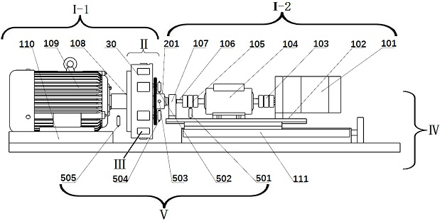
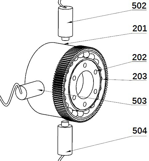
[0028] refer to Figure 1~13 , the internal force dissipation torque balance type harmonic drive double flexible member performance test device, including drive system (І), follow-up loading system (II), heat dissipation system (III), support system (IV) and data acquisition and processing system (V). The follow-up loading system (II) is fixed on the drive system (І) through bolt connection, and the cooling system (III) itself is a part of the follow-up loading system (II). The drive system (І) is connected to the follow-up loading system (II) and the tested components—flexible splines (201) and flexible bearings (203) for driving respectively. The follower loading system (II) uses the friction torque generated by the friction bearings (4003, 4103) to balance the external moment load, and applies a tangential load to the flexspline (201) through the elastic loading gear (4002, 4102) therein, The work done by it is converted into frictional heat and dissipated by the air cool...
Embodiment 2
[0030] refer to figure 1 and Figure 13 , the internal force dissipation torque balance type harmonic drive double flexible component performance test device, wherein the drive system (І) is divided into the main drive system (І-1) that drives the follower loading system (II) and the flexspline (201) driven slave drive system (І-2); main drive system (І-1) includes flange (108), motor armor (109), follower loader (30), wave generator (202) , flexible bearing (203), etc., the power source is the motor armor (109), and the flange (108) is connected to the follower loader (30) through a key, and the inner ring of the flexible bearing, the follower loader (30) and The loading device (400, 410) is driven; wherein the follower loader (30) is connected to the flange (108) by bolts, and there is a circular boss (301) in the center of the follower loader (30), which can place the flexible bearing ( 203) assembled with the wave generator (202) is installed on the boss (301), and the l...
Embodiment 3
[0035] refer to figure 1 , 6and 10, the follow-up loading system (II) is composed of a follow-up loader (30) and two loading devices (400, 410), the loading devices (400, 410) include loading nuts (4006, 4106), Loading springs (4005, 4105), sliding support blocks (4004, 4104), friction bearings (4003, 4103), spring loaded gears (4002, 4102), or loading straps (4012, 4112), and bolts (4001, 4101) ; The follow-up loading system (II) rotates synchronously with the inner ring of the tested flexible bearing, and can synchronously apply radial and tangential combined loads on the long axis of the outer ring of the flexible bearing (203); the follow-up loader (30 ) is disc-shaped, passes the center of circle of the follower loader (30) along the radial direction, and is processed with a guide post hole and a square groove at its 1 / 2 width place, inserts the guide post (302) in the guide post hole ), there is a threaded hole in the center of the disc, and the guide post (302) can be...
PUM
 Abstract
Description
Claims
Application Information
 - R&D
- Intellectual Property
- Life Sciences
- Materials
- Tech Scout
- Unparalleled Data Quality
- Higher Quality Content
- 60% Fewer Hallucinations
Browse by: Latest US Patents, China's latest patents, Technical Efficacy Thesaurus, Application Domain, Technology Topic, Popular Technical Reports.
© 2025 PatSnap. All rights reserved.Legal|Privacy policy|Modern Slavery Act Transparency Statement|Sitemap|About US| Contact US: help@patsnap.com


