
Supercritical carbon dioxide solar power generation and energy storing integrating system

A carbon dioxide and supercritical technology, which is applied in solar thermal power generation, electric energy storage systems, and mechanical power generation with solar energy, can solve problems such as low power generation efficiency, solar energy instability, and power grid shocks

Active Publication Date: 2019-02-15
INST OF ENGINEERING THERMOPHYSICS - CHINESE ACAD OF SCI
View PDF7 Cites 20 Cited by
  • Summary
  • Abstract
  • Description
  • Claims
  • Application Information

AI Technical Summary

Problems solved by technology

[0003] The thermal utilization of solar energy mainly includes solar water heaters, photovoltaic power generation, etc., but these power generation methods have two outstanding problems, one is that the power generation efficiency is not high, and the other is that although solar energy is clean energy, solar energy is very unstable, and the grid load itself It is also constantly fluctuating, solar energy is easy to bring impact to the grid, so it is also called garbage power

Method used


Image

  • Supercritical carbon dioxide solar power generation and energy storing integrating system
  • Supercritical carbon dioxide solar power generation and energy storing integrating system

Examples


Embodiment 1

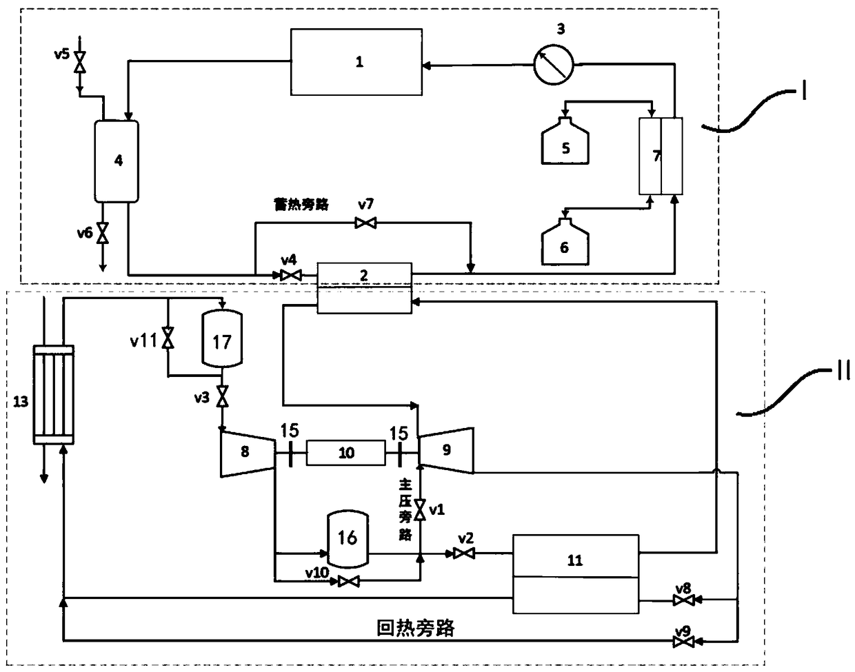
[0041] Such as figure 1 As shown, the supercritical carbon dioxide solar power generation and energy storage integrated system of this embodiment includes a solar heat collection heat storage unit I and a power unit II. Among them, the solar heat collection heat storage unit I includes a solar heat collector 1, a heater 2, a heat conduction oil pump 3, an expansion tank 4, a low-temperature molten salt storage tank 5, a high-temperature molten salt storage tank 6, and an oil-salt heat exchanger 7, The heater 2 is a heat transfer oil / supercritical carbon dioxide heat exchanger, the solar heat collector 1, the expansion tank 4, the high temperature side of the heater 2, the heat transfer oil heat exchange side of the oil-salt heat exchanger 7, the heat conduction The oil pump 3 is sequentially connected through pipelines to form a circulation loop, and a heat storage bypass with a control valve v7 is set between the inlet pipeline and the outlet pipeline on the high temperature ...

Embodiment 2

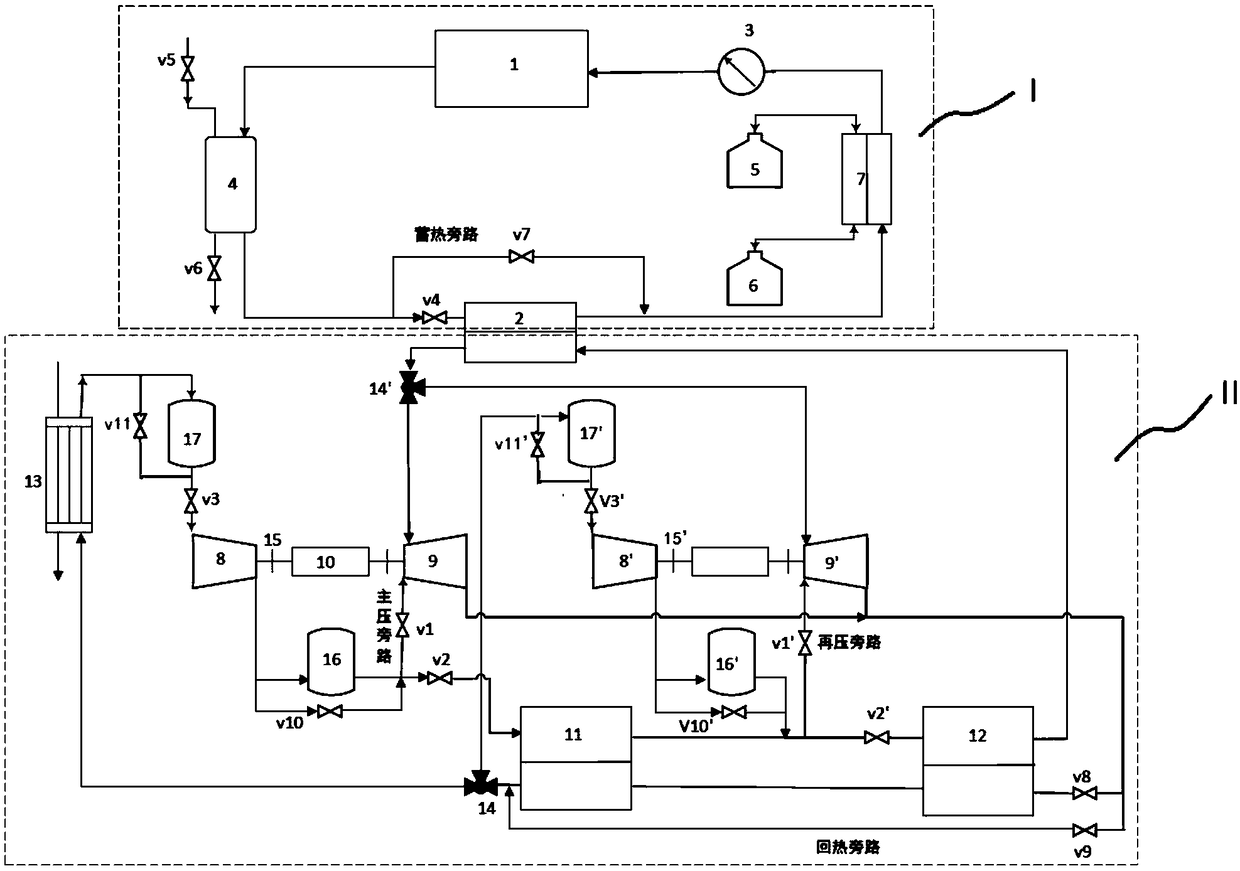
[0049] figure 2It is a structural schematic diagram of Embodiment 2 of the present invention, wherein the structure and working method of the solar heat collection and storage unit I are exactly the same as those of Embodiment 1. The difference from Embodiment 1 is that the power unit II of this embodiment also Including the second compressor 8', the second turbine 9', the second motor / generator 10', the second regenerator 12, the first splitter 14, the second splitter 14', the second high-pressure supercritical carbon dioxide The storage tank 16' and the second low-pressure supercritical carbon dioxide storage tank 17', wherein the inlet of the second compressor 8' and the outlet of the second low-pressure supercritical carbon dioxide storage tank 17' pass through a valve with a valve v3 ', the exhaust port of the second compressor 8' communicates with the inlet of the second high-pressure supercritical carbon dioxide storage tank 16'; the outlet of the first high-pressure s...


PUM


Abstract

The invention discloses a supercritical carbon dioxide solar power generation and energy storing integrating system. The whole system is applicable to the fields of renewable energy sources and intelligent power grids. The system comprises the following main devices: a solar heat collector, a heat exchanger, a heat transferring oil pump, a pipeline, a fuse salt storing tank, a valve, a main compressor, a recompression device, a high-temperature heat regenerator, a low-temperature heat regenerator, a turbine, an engine / power generation machine, a condenser, a clutch, a control system, etc. Thesystem is applicable to solar heat power generation and is capable of acquiring energy from power grids to assist peak load regulation of the power grids; in addition, the redundancy for the devicesis reduced, and thus the system reliability is improved.

Description

technical field [0001] The invention belongs to the fields of solar thermal power generation, smart grid and distributed energy, and relates to a solar energy utilization technology, in particular to a supercritical carbon dioxide solar power generation and energy storage integrated system. Background technique [0002] Due to the development of fossil energy, problems such as smog, acid rain, and photochemical smog have become prominent. In addition, fossil energy is a non-renewable energy source, so renewable energy sources such as solar energy, wind energy, and biomass energy should be used as much as possible. Developing solar energy and increasing the proportion of solar energy in power sources can help solve energy shortages and environmental pollution problems. [0003] The heat utilization of solar energy mainly includes solar water heaters, photovoltaic power generation, etc., but these power generation methods have two outstanding problems, one is that the power ge...

Claims


Application Information

Patent Timeline
IPC IPC(8): F03G6/06F01K11/02F01K25/10H02J3/28H02J15/00
CPCF01K11/02F01K25/103F03G6/06H02J3/28H02J15/00Y02E10/46Y02E70/30
Inventor 赵庆军赵巍周小勇项效镕崔伟伟
Owner INST OF ENGINEERING THERMOPHYSICS - CHINESE ACAD OF SCI
Learn More