Dual-sucking energy-saving beam-pumping unit

A beam pumping unit and beam beam technology, applied in the fields of production fluid, wellbore/well components, earthwork drilling and production, etc., can solve the problems of unbalanced two oil wells, lower power factor of power distribution lines, maintenance and repair difficulties And other issues

Pending Publication Date: 2019-02-15
杭州中油智井装备科技有限公司
View PDF1 Cites 6 Cited by
  • Summary
  • Abstract
  • Description
  • Claims
  • Application Information

AI Technical Summary

Problems solved by technology

[0003] The beam pumping unit is a kind of oil production equipment widely used in major oil fields. There are many variant products, but the principle is basically the same. They all use a four-bar linkage mechanism to convert the rotary motion of the gearbox into a beam pumping unit. At present, about 70% of the pumping unit motors have an average load of less than 40%, and their operating efficiency is lower than 80%. The loss increases, and the reason for this phenomenon is that the beam pumping unit adopts a four-bar linkage mechanism, the static moment is relatively large when starting, the suspension point load is alternating during normal operation, and the load characteristics are also alternating. Therefore, in order to overcome the static load moment of the load at startup, the motor capacity can only be increased, resulting in waste. Therefore, if the four-link drive mode of the beam pumping unit can be changed and the counterweights at the left and right ends of the beam can be flexibly adjusted, Reduce the starting static load torque, you can choose a smaller power motor, improve operating efficiency, and effectively improve the energy saving effect
[0004] Patent Publication No. CN202451116U "A Double Suction Energy-Saving Vertical Pumping Unit" provides a double-suction energy-saving pumping unit, including: a base, a frame, a column, a power drive system and an electrical control system. There are guide wheels on the top, and fixed pulleys on the frame. The wheels are connected to the power drive system and the electrical control system through wire ropes, and the wire ropes on the left and right sides are connected to the same counterweight box. The double pumping unit provided by this patent has the advantages of There is only one counterweight box. Under the working condition that the pumping depths of the two oil wells are different, only one counterweight box can not achieve the balanced state of the two oil wells, and the best energy-saving effect cannot be achieved. In addition, the transmission mechanism of the double pumping unit It is relatively complicated, and there are certain difficulties in maintenance and repair under running conditions

Method used


Image

  • Dual-sucking energy-saving beam-pumping unit
  • Dual-sucking energy-saving beam-pumping unit
  • Dual-sucking energy-saving beam-pumping unit

Examples


Embodiment Construction

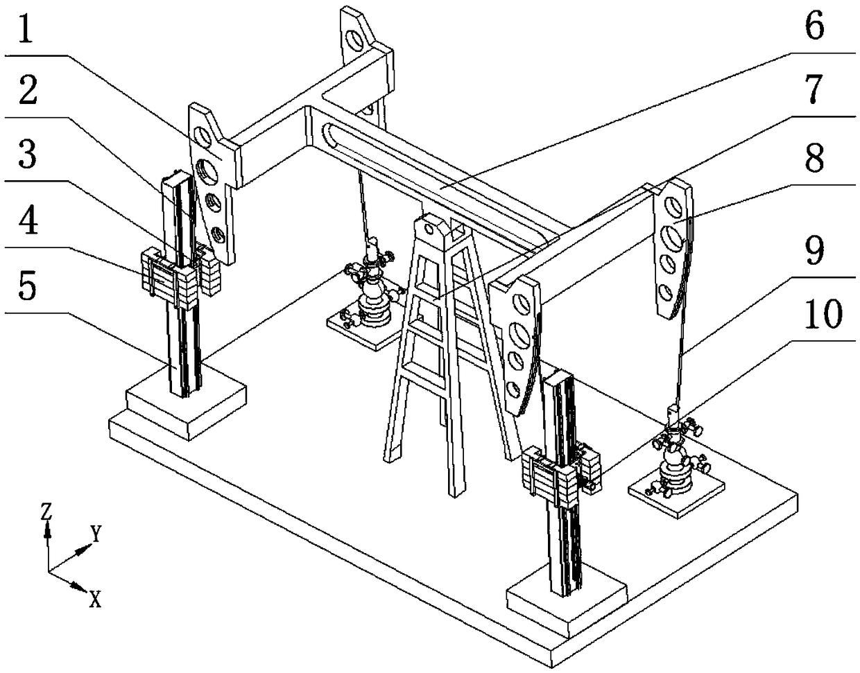
[0020] Such as figure 1 As shown, a double pumping energy-saving beam pumping unit includes: sucker rod 9, driving donkey head 1, load donkey head 8, traveling beam 6, traveling beam frame 7, driving rope 2 and drive system, such as figure 2 , 3 As shown, the driving system is composed of a driving unit 10, a traction unit 3, a counterweight unit 4 and a support column 5. The structure of the present invention is symmetrically distributed in the X direction, and each end of the beam includes a driving donkey head 1 and a load donkey. The heads 8 are distributed symmetrically in the Y direction. The drive heads 1 on both sides are respectively connected to the traction unit 3 of the drive system on the corresponding side through the drive rope 2. The load heads 8 on both sides are respectively connected to the sucker rods 9 on the corresponding side. .

[0021] Such as Figure 4 , 5 As shown, the drive unit 10 consists of a three-phase asynchronous motor 10-1, a speed redu...


PUM


Abstract

The invention discloses a dual-sucking energy-saving beam-pumping unit. The dual-sucking energy-saving beam-pumping unit comprises sucker rods, driving horseheads, loading horseheads, a beam, a beam frame, driving wires and driving systems. The two ends of the beam is symmetric and all comprise one driving horseheads and one loading horseheads, the driving horseheads are connected with the corresponding driving systems through the driving wires, the loading horseheads are connected with the corresponding sucker rods, the structures of the driving systems on the two sides are the same, and thedriving systems all comprise driving units, traction units and counter weight units.When the left side driving unit moves downward, the left side traction unit draws the left side driving horsehead tomove downward, the left side loading horsehead and the left side sucker rod move downward, the right side loading horsehead draws the right sidesucker rod to move upward under the action of driving force of the left side driving system, and meanwhile, the right side driving unit moves upward initiatively, and the moving speed is higher than the downward moving speed of the left side driving unit,a right side counter weight fails to work, and back and forth. The dual-sucking energy-saving beam-pumping unit is driven by a gear and a gear rack, the counter weight can be adjusted correspondinglyaccording to actual working conditions of two wells, the balancing property is good, and the energy-saving effect is significant.

Description

technical field [0001] The invention relates to a double pumping energy-saving beam pumping unit driven by a rack and pinion and capable of separately adjusting the required counterweights of two oil wells. Background technique [0002] With the continuous deepening of oilfield development, in order to increase crude oil production, save equipment and land acquisition costs, cluster wells and land infill wells are increasing. The spacing between cluster wellheads is generally within 7-10m. If the traditional method of one machine and one well is used for mining, it will cause huge equipment costs and waste of electric energy. Therefore, taking advantage of the characteristics of the platform wells with close spacing, a pumping unit structure using one pumping unit with two wells has emerged. Realize that one pumping unit can exploit two oil wells at the same time, and adopting double-well pumping units can effectively save investment in oil field equipment and reduce energy ...

Claims


Application Information

Patent Timeline
IPC IPC(8): E21B43/00E21B43/12
CPCE21B43/00E21B43/121E21B43/127
Inventor 魏燕定王彦哲方升何光玉宋执环
Owner 杭州中油智井装备科技有限公司
Why Eureka
Try Eureka