
Latex centrifuge cleaning system and method

A cleaning system and centrifuge technology, applied in centrifuges and other directions, can solve the problems of large influence of centrifugal disc rotational inertia and difficult operation process, and achieve the effect of effective cleaning and speeding up cleaning efficiency.

Pending Publication Date: 2019-02-15
QINGDAO UNIV OF SCI & TECH
View PDF6 Cites 5 Cited by
  • Summary
  • Abstract
  • Description
  • Claims
  • Application Information

AI Technical Summary

Problems solved by technology

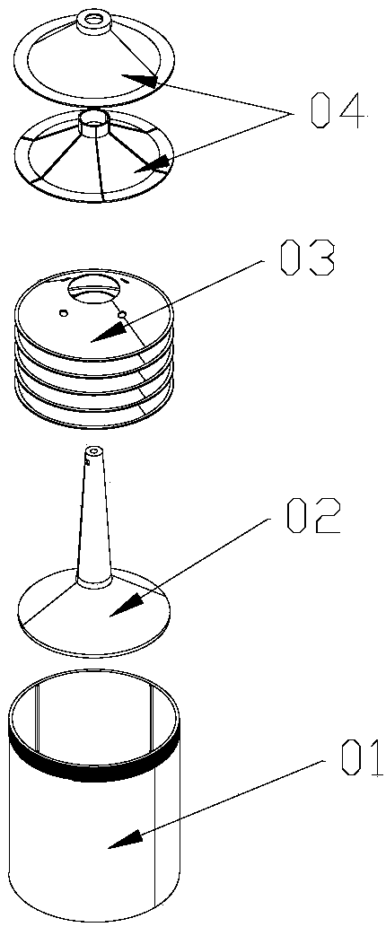
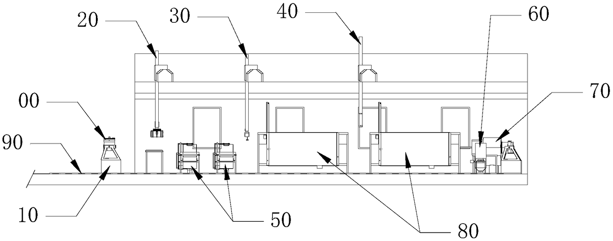
[0008] In order to solve the problem that the existing latex centrifuge adopts manual cleaning, the operation process is difficult, and the problem of great influence on the moment of inertia of the centrifugal disc before and after cleaning, the present invention provides a latex centrifuge cleaning system, including: a moving device for driving The latex centrifuge moves; the dismounting device is used to disassemble and install the lock nut on the latex centrifuge; the grabbing device is used to grab the gland, the centrifugal shaft and the centrifugal disc on the latex centrifuge; A cover cleaning device for cleaning the gland of the latex centrifuge; a centrifugal shaft cleaning device for cleaning the centrifugal shaft of the latex centrifuge; a centrifugal drum cleaning device for cleaning the centrifugal drum of the latex centrifuge; The centrifugal disk cleaning device is used to clean the centrifugal disk of the latex centrifuge; the track, the moving device runs on the track, the disassembly device, the grabbing device, the gland cleaning device, the centrifugal disk Cleaning device, centrifugal drum cleaning device, and centrifugal shaft cleaning device are arranged on one side of the track in sequence

Method used


Image

  • Latex centrifuge cleaning system and method
  • Latex centrifuge cleaning system and method
  • Latex centrifuge cleaning system and method

Examples


Embodiment Construction

[0037] It should be noted that, in the case of no conflict, the embodiments of the present invention and the features in the embodiments can be combined with each other.

[0038] In the description of the present invention, it should be understood that the orientations and positional relationships indicated by the terms "upper", "lower", "front", "rear", "left", "right" etc. The positional relationship is only for the convenience of describing the present invention and simplifying the description, but does not indicate or imply that the referred device or component must have a specific orientation, be constructed and operated in a specific orientation, and thus should not be construed as a limitation of the present invention. In addition, the terms "first", "second", etc. are used for descriptive purposes only, and should not be interpreted as indicating or implying relative importance or implicitly specifying the quantity of the indicated technical features. Thus, a feature d...


PUM


Abstract

The invention discloses a latex centrifuge cleaning system. The latex centrifuge cleaning system comprises a moving device used for driving a latex centrifuge to move, a disassembling and assembling device used for disassembling and assembling a locking nut on the latex centrifuge, a gripping device used for gripping glands, a centrifugal shaft and centrifugal discs on the latex centrifuge, a gland cleaning device used for cleaning the glands of the latex centrifuge, a centrifugal shaft cleaning device used for cleaning the centrifugal shaft of the latex centrifuge, a centrifugal drum cleaningdevice used for cleaning a centrifugal drum of the latex centrifuge and a centrifugal disc cleaning device used for cleaning the centrifugal discs of the latex centrifuge, specifically, the moving device runs on a track, and the disassembling and assembling device, the gripping device, the gland cleaning device, the centrifugal disc cleaning device, the centrifugal drum cleaning device and the centrifugal shaft cleaning device are sequentially arranged on one side of the track. In the centrifugal disc cleaning process, the original positions of the centrifugal discs are kept invariable, one-time effective centrifugal disc cleaning is achieved, and the cleaning efficiency is greatly improved.

Description

technical field [0001] The invention relates to rubber processing machinery, in particular to a latex centrifuge cleaning system. Background technique [0002] The wide use of rubber products around the world has increased the demand for latex, the rubber raw material. There are only 30% natural rubber in the latex cut from the rubber tree. In order to increase the rubber solubility in the latex and save transportation costs, manufacturers use latex centrifuges to increase the concentration of natural rubber in the latex. [0003] Fresh latex in the gravitational field, because the gravity of rubber particles and whey is not much different, the diameter of rubber particles is very small, it is impacted by the thermal movement of water molecules in whey to make irregular movements, plus the protective layer of rubber particles Hydrophilicity and negative charge, therefore, the separation speed of rubber particles and emulsion is very slow. Concentrating latex by centrifugat...

Claims


Application Information

Patent Timeline
Patent Type & Authority Applications(China)
IPC IPC(8): B04B15/06
CPCB04B15/06Y02W30/62
Inventor 边慧光赵百顺张骞汪传生李绍明范文超田晓龙田绪东
Owner QINGDAO UNIV OF SCI & TECH
Learn More