
Power device and manufacturing method thereof

A technology of power devices and manufacturing methods, applied in semiconductor/solid-state device manufacturing, semiconductor devices, electrical components, etc., can solve problems such as increased on-resistance, difficulty in realizing super-junction power devices, and increased difficulty in process control of super-junction power devices , to achieve the effect of low on-resistance and high breakdown voltage

Pending Publication Date: 2019-02-12
上海昱率科技有限公司
View PDF0 Cites 3 Cited by
  • Summary
  • Abstract
  • Description
  • Claims
  • Application Information

AI Technical Summary

Problems solved by technology

When the demand for breakdown voltage further increases to a certain value (such as above 900V), the process control difficulty of super-junction power devices will increase, and the product yield and reliability will become unstable. At the same time, the on-resistance will also increase sharply, so high Breakdown voltage super junction power devices become difficult to achieve

Method used


Image

  • Power device and manufacturing method thereof
  • Power device and manufacturing method thereof
  • Power device and manufacturing method thereof

Examples


Embodiment Construction

[0022] Hereinafter, embodiments of the present disclosure will be described with reference to the drawings. It should be understood, however, that these descriptions are exemplary only, and are not intended to limit the scope of the present disclosure. Also, in the following description, descriptions of well-known structures and techniques are omitted to avoid unnecessarily obscuring the concepts of the present disclosure.

[0023] Various structural schematic diagrams according to embodiments of the present disclosure are shown in the accompanying drawings. The figures are not drawn to scale, with certain details exaggerated and possibly omitted for clarity of presentation. The shapes of the various regions and layers shown in the figure, as well as their relative sizes and positional relationships are only exemplary, and may deviate due to manufacturing tolerances or technical limitations in practice, and those skilled in the art will Regions / layers with different shapes, ...


PUM


Abstract

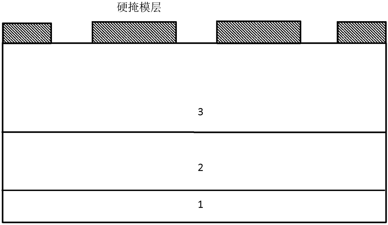
The invention relates to a power device which comprises a substrate, a first epitaxial layer, a second epitaxial layer, a plurality of first body areas and a plurality of second body areas. The firstepitaxial layer is arranged on the substrate, the second epitaxial layer is arranged on the first epitaxial layer, the first body areas are arranged in the second epitaxial layer, the second body areas are arranged under the corresponding first body areas and extend into the first epitaxial layer downwards from the second epitaxial layer, and the bottoms of the second body areas are positioned inthe first epitaxial layer.

Description

technical field [0001] The present disclosure relates to the field of semiconductors, and in particular, to a power device, a manufacturing method thereof, and an electronic device including the power device. Background technique [0002] Traditional power devices (for example, VDMOS) need to reduce the doping concentration of the drift region or increase the thickness of the drift region in order to withstand high withstand voltage, which directly results in a sharp increase in the on-resistance. In order to overcome the above problems, super-junction power devices (eg, super-junction MOSFETs) are receiving more and more attention. Based on the principle of charge compensation, the super-junction MOSFET makes the on-resistance and breakdown voltage of the device have a 1.32 power relationship, which well solves the contradiction between on-resistance and breakdown voltage. Compared with the traditional power VDMOS structure, the super-junction MOSFET uses multiple columnar...

Claims


Application Information

Patent Timeline
Patent Type & Authority Applications(China)
IPC IPC(8): H01L29/786H01L29/06H01L21/336
CPCH01L29/0623H01L29/0634H01L29/0684H01L29/66742H01L29/78606
Inventor 杨东林刘侠陈文高
Owner 上海昱率科技有限公司
Learn More