A kind of software and hardware control high reliable switching machine circuit
What is Al technical title?
Al technical title is built by PatSnap Al team. It summarizes the technical point description of the patent document.
A switching circuit, software and hardware technology, applied in the field of power electronics, can solve problems such as affecting the normal switching of equipment, harsh environmental conditions, poor contact of power-on switches, etc.
Active Publication Date: 2022-05-03
江苏绿城信息技术有限公司
View PDF8 Cites 0 Cited by
Summary
Abstract
Description
Claims
Application Information
AI Technical Summary
This helps you quickly interpret patents by identifying the three key elements:
Problems solved by technology
Method used
Benefits of technology
Problems solved by technology
[0003] However, in the actual use of the equipment, the environmental conditions are harsh, such as vibration and electromagnetic interference, there will be a phenomenon that the power switch is shaken and the contact is poor or the microprocessor is disturbed and crashed, thus affecting the normal switching of the equipment.
Method used
Image
Click on the blue label to locate the original text in one second.
Reading with bidirectional positioning of images and text.
Examples
Embodiment Construction
[0011] The technical solution of the present invention will be further described in detail below in conjunction with the accompanying drawings and embodiments.
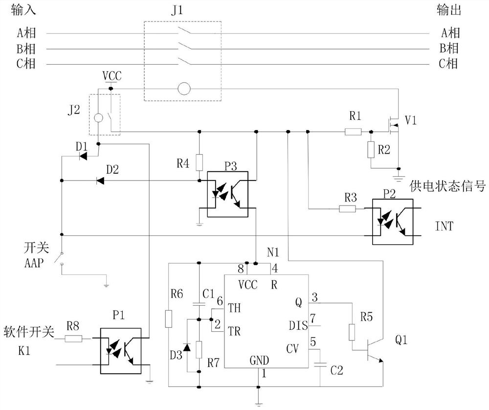
[0012] to combine figure 1 , the software and hardware control high reliability switching machine circuit of the present invention includes contactor J1, relay J2, switch AAP, software hold switch K1, field effect transistor V1, optocoupler P1, optocoupler P2, resistor R1, resistor R2, Resistor R3, resistor R4, diode D1, one end of the switch AAP is grounded, the other end is connected to the relay J2 through the diode D1, one end of the relay J2 is connected to the drain of the field effect transistor V1 through the contactor J1, and the other end is connected to the field through the resistor R1. The gate of the effect transistor V1, one end of the resistor R2 is connected to the gate of the field effect transistor V1, the other end is grounded to the source of the field effect transistor V1, one end of the photocou...
PUM
Abstract
The invention relates to a highly reliable switch machine circuit controlled by software and hardware, including a contactor J1, a relay J2, a switch AAP, a software hold switch K1, a field effect transistor V1, an optocoupler P1, an optocoupler P2, a resistor R1, a resistor R2, a resistor R3, resistor R4, diode D1, one end of the switch AAP is grounded, the other end is connected to the relay J2 through the diode D1, one end of the relay J2 is connected to the drain of the field effect transistor V1 through the contactor J1, and the other end is connected to the field effect transistor V1 through the resistor R1. The gate of the transistor V1, one end of the resistor R2 is connected to the gate of the field effect transistor V1, the other end is grounded to the source of the field effect transistor V1, one end of the photocoupler P2 is connected to the switch AAP, and the other end is connected to the relay J2 through the resistor R3, The software hold switch K1 is connected to the photocoupler P1 through the resistor R8, and the photocoupler P1 is connected to the relay J2. In order to ensure the reliable power supply of the equipment, the software interlock signal is sent out through the microcontroller, and the software and hardware double ensure the reliable pull-in of the contactor contacts.
Description
technical field [0001] The invention relates to the technical field of power electronics, in particular to a highly reliable switch machine circuit controlled by software and hardware. Background technique [0002] With the continuous development of computer technology, most electrical equipment is controlled by microprocessors, and there are generally two ways to control the power supply of electrical equipment. One uses alternating current or direct current to directly apply to the switch, and the equipment is powered by turning on and off the switch, and the main circuit current flows through the switch, which requires a high current and voltage resistance of the switch. A contact that uses alternating current or direct current to add to the relay or contactor. The power switch is connected to the wire package of the relay or contactor, and the contact of the relay or contactor is closed and disconnected by turning on and off the power switch. , to power up the equipment...
Claims
Application Information
Patent Timeline
Application Date:The date an application was filed.
Publication Date:The date a patent or application was officially published.
First Publication Date:The earliest publication date of a patent with the same application number.
Issue Date:Publication date of the patent grant document.
PCT Entry Date:The Entry date of PCT National Phase.
Estimated Expiry Date:The statutory expiry date of a patent right according to the Patent Law, and it is the longest term of protection that the patent right can achieve without the termination of the patent right due to other reasons(Term extension factor has been taken into account ).
Invalid Date:Actual expiry date is based on effective date or publication date of legal transaction data of invalid patent.