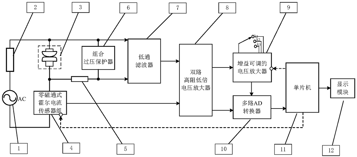
Circuit for testing voltage drop of contact in electrical life experiment of AC electric appliance
A technology of experimental process and electrical life, applied in circuit breaker testing, voltage/current isolation, measuring current/voltage, etc., can solve the problems of low input impedance, slow conversion speed, poor test accuracy, etc., to achieve simple test process, The effect of taking into account the test accuracy and improving the measurement range
- Summary
- Abstract
- Description
- Claims
- Application Information
AI Technical Summary
Problems solved by technology
Method used
Image
Examples
specific Embodiment approach 1
[0010] Specific implementation mode one: the following combination figure 1 This embodiment will be specifically described. This embodiment includes an AC voltage source 1, a load 2, a pair of contacts under test 3, a zero-flux Hall current sensor group 4, a current limiting resistor 5, a low-pass filter 7, and a dual-channel high-resistance low-voltage amplifier 8 , a gain-adjustable voltage amplifier 9, a multi-channel AD converter 10, a single-chip microcomputer 11 and a display module 12, one electrode of the AC voltage source 1 is connected to one end of the load 2, and the other end of the load 2 is connected to the contact pair 3 under test. One contact and a signal input terminal of the low-pass filter 7, the other electrode of the AC voltage source 1 passes through the zero-flux type Hall current sensor group 4, and connects the other contact of the measured contact pair 3 and the limiter. One end of the current-limiting resistor 5, the other end of the current-limit...
specific Embodiment approach 2
[0027] Specific implementation mode two: the following combination figure 1 This embodiment will be specifically described. The difference between this embodiment and Embodiment 1 is that it also includes a combined overvoltage protector 6, and the two terminals of the combined overvoltage protector 6 are respectively connected to the two signal input terminals of the low-pass filter 7;
[0028] The combined overvoltage protector is composed of a transient suppression diode and a Zener diode connected in parallel.
[0029] When the two electrical contacts are disconnected, the voltage U across the measured contact pair 3 Ci Equal to the voltage of the AC voltage source 1, at this time the current limiting resistor 5 and the combined overvoltage protector 6 can limit the input voltage of the low-pass filter 7 within a safe range; when the two electrical contacts are closed, the combined overvoltage protector 6 Not working.
[0030] From the current methods of testing the con...
PUM
 Abstract
Description
Claims
Application Information
 - R&D Engineer
- R&D Manager
- IP Professional
- Industry Leading Data Capabilities
- Powerful AI technology
- Patent DNA Extraction
Browse by: Latest US Patents, China's latest patents, Technical Efficacy Thesaurus, Application Domain, Technology Topic, Popular Technical Reports.
© 2024 PatSnap. All rights reserved.Legal|Privacy policy|Modern Slavery Act Transparency Statement|Sitemap|About US| Contact US: help@patsnap.com


