Device and method for dynamically measuring accumulation thickness of debris flow
A technology of dynamic measurement and debris flow, which is applied in the direction of measuring devices, instruments, and wave/particle radiation, can solve the problem of inability to measure the thickness of dynamic debris flow accumulation, and achieve the effect of improving rescue efficiency, reducing floor space, and compact overall structure
- Summary
- Abstract
- Description
- Claims
- Application Information
AI Technical Summary
Problems solved by technology
Method used
Image
Examples
Embodiment 1
[0045] A method for dynamically measuring the thickness of debris flow accumulation, comprising the following steps:
[0046] S1. Determine different water contents through pre-experiment with different porosity Debris slurry thickness The linear relationship between X-ray and X-ray, such as the following formula;
[0047]
[0048] In the above formula, is the absorption constant of the material, tubes with exposed material, is the relative gray value;
[0049] in for: ,in is the total mass of the material, is the total volume of the material.
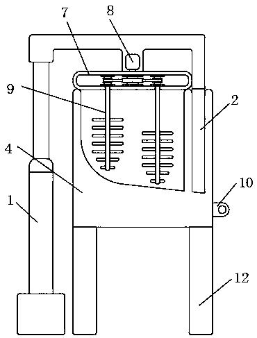
[0050] S2. Add materials to the inside of the italic mixing tank 4 and stir. After the materials have been stirred, take multiple groups of samples to measure the water content of the materials in the natural environment and porosity , and measure the total mass of the material and total volume ;
[0051] S3, after the measurement is completed, start the drive device 15 to adjust the angle between the co...
Embodiment 2
[0063] Embodiment 2: the difference based on Embodiment 1 is;
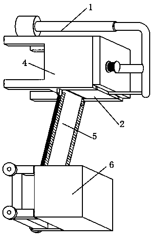
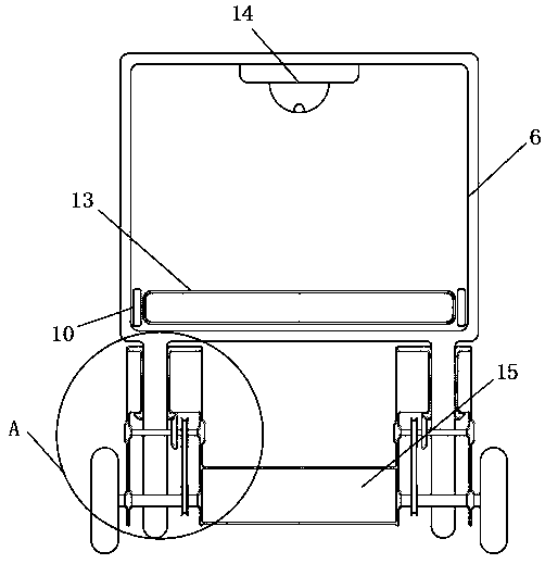
[0064] A device for dynamically measuring the thickness of debris flow accumulation, including a hydraulic rod 1, an oblique mixing tank 4, a connecting plate 5, a driving device 15, and a dark box 6, as well as a mobile support column 22 and a sealing door 2, the middle part of the upper end of the hydraulic rod 1 and the left middle The upper end of the sealing cover 7 is fixedly connected, the inside of the sealing cover 7 is fixedly installed with a stirring device, the left side of the upper end of the hydraulic rod 1 is fixedly connected with the upper end of the sealing door 2, the upper end of the italic mixing tank 4 is movably connected with the lower surface of the sealing cover 7, and the italic mixing tank 4 is on the right A sealing door 2 is movable in the side inner wall, the lower end of the italic mixing tank 4 is fixedly connected with the upper end of the supporting base 12, the right side of th...
Embodiment 3
[0068] Embodiment 3: the difference based on embodiment 1 and 2 is;
[0069] The left and right sides of the feed hole 13 and the front and rear sides of the bottom end of the italic mixing tank 4 are fixedly equipped with a fixed base 10, and a limit shaft 16 is fixedly installed between the fixed bases 10, and the connecting plate 5 is provided with a sliding groove 11 inside to slide. The upper and lower ends of the groove 11 are provided with a rotating groove 17, and the inside of the rotating groove 17 is movably socketed with a limiting shaft 16.
[0070] The present invention is also provided with a connecting plate 5. When in use, by placing the limit shaft 16 on the fixed base 10 inside the rotating groove 17, the angle of the connecting plate 5 can be easily changed. When the device needs to be put away After the height of the dark box 6 is lowered to a suitable height, the limit shaft 16 can be moved to the inside of the rotation groove 17, and then the connecting ...
PUM
 Abstract
Description
Claims
Application Information
 - R&D
- Intellectual Property
- Life Sciences
- Materials
- Tech Scout
- Unparalleled Data Quality
- Higher Quality Content
- 60% Fewer Hallucinations
Browse by: Latest US Patents, China's latest patents, Technical Efficacy Thesaurus, Application Domain, Technology Topic, Popular Technical Reports.
© 2025 PatSnap. All rights reserved.Legal|Privacy policy|Modern Slavery Act Transparency Statement|Sitemap|About US| Contact US: help@patsnap.com


