Prestressed hollow sandwich concrete-filled steel tube wind power tower barrel and combined foundation thereof

A concrete-filled steel tube and combined foundation technology, which is applied in the field of onshore wind power generation and low wind speed and high towers, can solve the problems of easy corrosion of steel towers, high maintenance costs, and increased costs, so as to reduce the cost of construction measures and construction. Convenience and the effect of reducing steel consumption

Pending Publication Date: 2019-02-01
CHONGQING UNIV
View PDF7 Cites 4 Cited by
  • Summary
  • Abstract
  • Description
  • Claims
  • Application Information

AI Technical Summary

Problems solved by technology

[0003] As the mainstream structural form of large-scale wind turbine towers, steel towers currently have the following problems: the cost increases exponentially with the increase of tower height; Resonance occurs in wind turbines; taking a 2MW unit as an example, when the height of the tower is greater than 90m, the diameter of the bottom is generally in the range of 4m to 4.7m, which exceeds the 4.5m height limit for general roads, and transportation is difficult; the steel tower is easy to corrode , high maintenance cost

Method used


Image

  • Prestressed hollow sandwich concrete-filled steel tube wind power tower barrel and combined foundation thereof
  • Prestressed hollow sandwich concrete-filled steel tube wind power tower barrel and combined foundation thereof
  • Prestressed hollow sandwich concrete-filled steel tube wind power tower barrel and combined foundation thereof

Examples


Embodiment Construction

[0023] The present invention will be further described below in conjunction with the drawings.

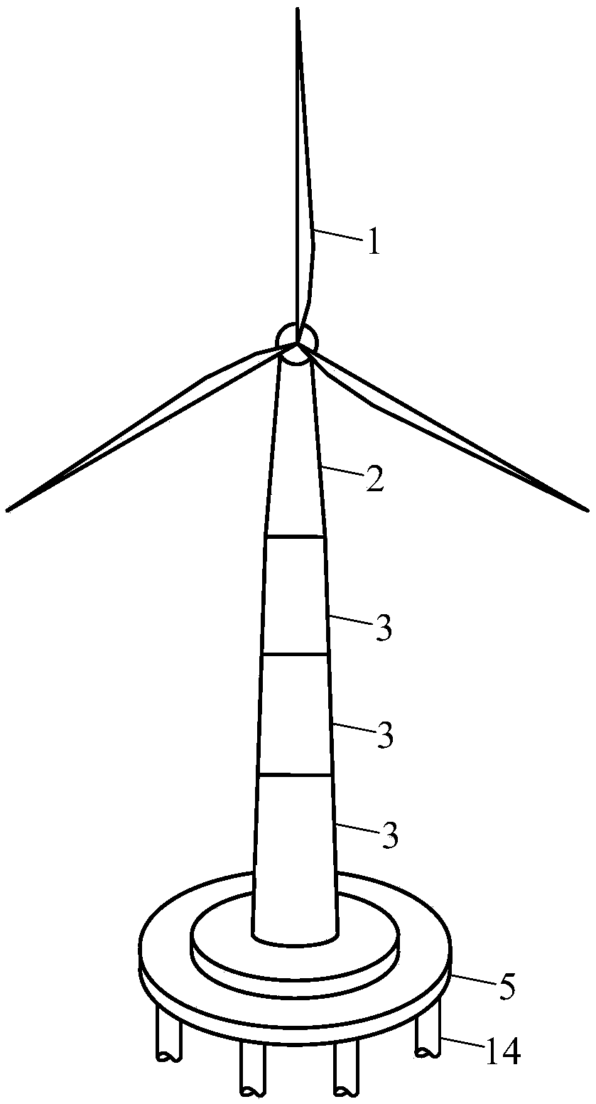
[0024] Such as figure 1 As shown, a prestressed hollow sandwich steel tube concrete wind power tower and its combined foundation. The system includes a wind turbine (1), an upper steel tower (2), a hollow sandwich steel tube concrete tower (3), and a cap (5) , Pile foundation (14); the hollow sandwich steel tube concrete tower (3) is prefabricated in sections, and high-strength grouting is poured between the sections to connect; the hollow sandwich steel tube concrete tower (3) and the foundation ( 5) Pouring high-strength grout connection between them.

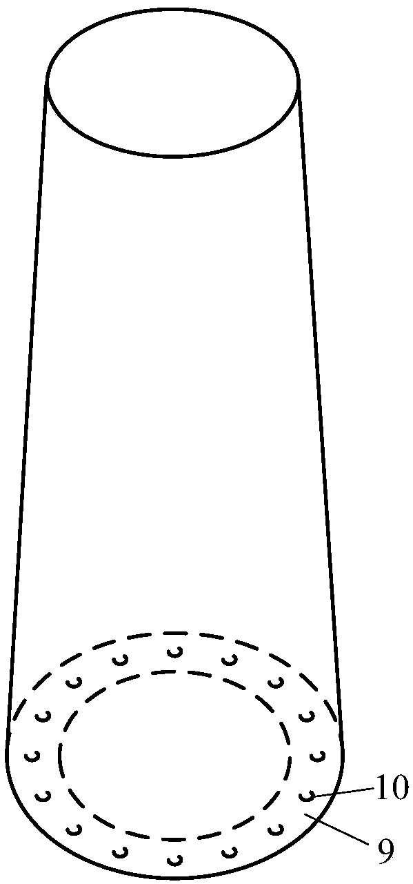
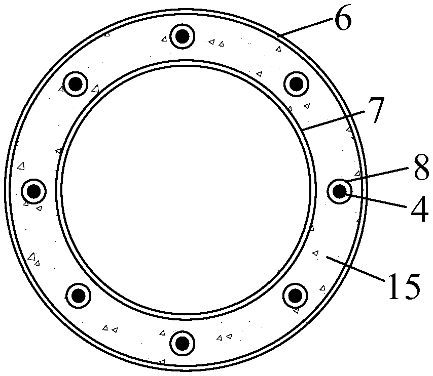
[0025] Such as figure 2 , Figure 4 As shown, the bolts (11) are pre-embedded on the top of the hollow sandwich steel tube concrete tower tube (3), and are connected with the flange (9) of the upper steel tower (2) on site.

[0026] Such as Figure 4 , Figure 5 As shown, in the hollow sandwich concrete-filled steel tube tower (3) and ...


PUM


Abstract

The invention discloses a prestressed hollow sandwich concrete-filled steel tube wind power tower barrel and a combined foundation thereof, and relates to the technical field of onshore wind power generation. A system comprises a fan, an upper steel tower, the hollow sandwich concrete-filled steel tube tower barrel, prestressed ribs, a cushion cap and pile foundations. The hollow sandwich concrete-filled steel tube tower barrel is prefabricated in sections, and high-strength grouting materials are adopted to connect the sections; bolts are embedded at the top of the hollow sandwich concrete-filled steel tube tower barrel to be connected with the upper steel tower. The prestressed ribs are located between the top of the hollow sandwich concrete-filled steel tube tower barrel and the bottomof the foundation and adopt a post-tensioning construction method. Welded studs and annular horizontal steel plates with vertical shear steel plates are arranged on the top of a cushion cap cavity. The system has simple structure, and good overall stability, and is a brand new onshore wind power tower barrel and foundation form. The system is very suitable for building low-wind-speed high-towers.The structural system adopts a fabricated construction method. The construction quality can be significantly guaranteed, the construction efficiency can be improved and the fee of construction measures can be reduced.

Description

Technical field [0001] The invention relates to the technical field of onshore wind power generation, in particular to the technical field of low wind speed and high tower. Background technique [0002] As a clean, renewable, low-carbon energy source, wind power has attracted more and more attention and attention. In recent years, with the continuous and rapid development of the global wind power industry, the average height of wind turbines has exceeded 80m. Larger impeller diameters and taller towers have become the mainstream trend of wind power development. As an important part of the wind generator, the main function of the tower is to support the impeller and the nacelle, and send the generator set to the design height to obtain enough wind energy to drive the generator to generate electricity. [0003] Steel towers are the mainstream structure of large wind turbine towers. At present, there are some problems: the cost increases exponentially as the height of the tower incre...

Claims


Application Information

Patent Timeline
IPC IPC(8): F03D13/20E02D27/42
CPCF03D13/20F03D13/22E02D27/425F05B2240/912Y02E10/728Y02E10/72
Inventor 周绪红王宇航王姝琪谭继可邓然
Owner CHONGQING UNIV
Why Eureka
Try Eureka