


Quick Research
Generate reliable direction feasibility study reports for your R&D in just a few steps.

Technical Q&A
Discover and master advanced knowledge NOW. Basics, ideas, possibilities, all at once.

Find Solutions
As an expert in R&D theories, this can generate solutions to your technical problems instantly.

Evaluate Feasibility
Analyze your overall solution with one click, know your potential R&D risks in advance.

Monitor Landscape
Get weekly tech updates, stay abreast of the latest tech innovations and key insights.
A jet dyeing equipment with good dyeing effect
A technology of dyeing effect and equipment, which is applied in the processing of textile materials, spraying/jetting textile materials, processing textile material drums, etc. Fast and efficient dyeing, simple structure, and the effect of reducing operation and maintenance costs
- Summary
- Abstract
- Description
- Claims
- Application Information
AI Technical Summary
Problems solved by technology
Method used
Image

Examples
Embodiment 1
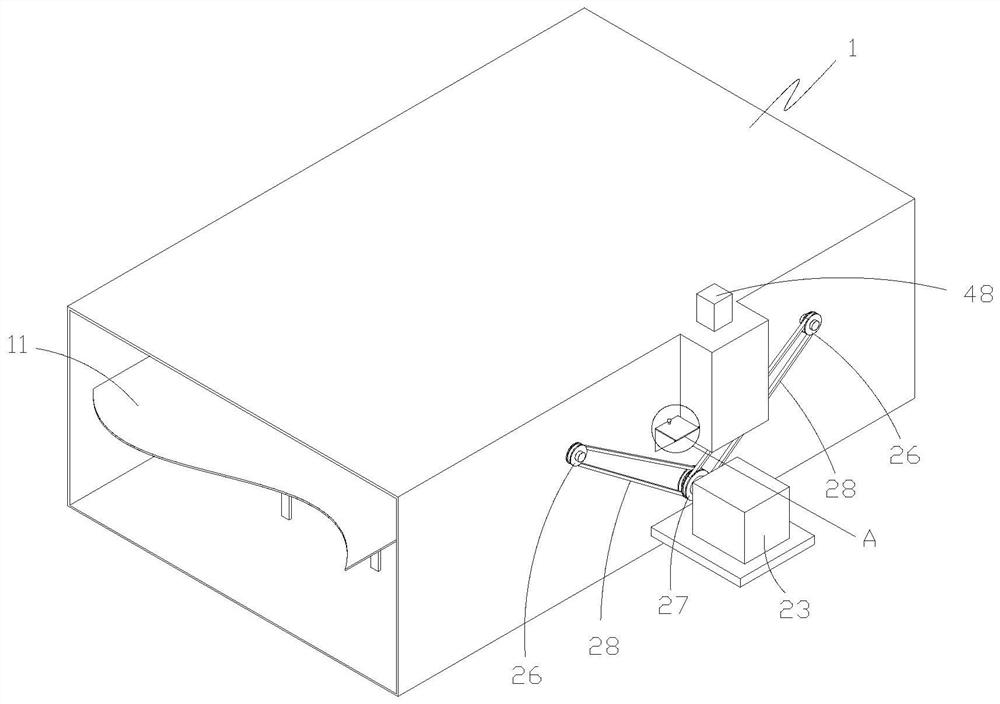
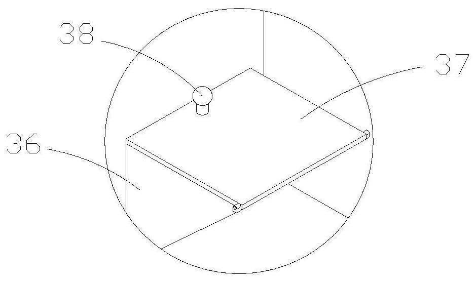
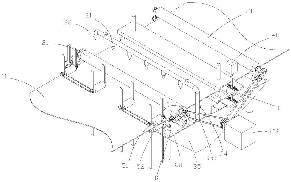
[0033] Such as Figure 1-8 As shown, a spraying and dyeing equipment with good dyeing effect includes a frame 1, a cloth 11, a driving device, a spraying device, a smearing device and a leveling device; wherein the driving device includes a roller shaft group, a first driving member 23 and a roller shaft transmission Structure; the first driving member is a motor purchased on the market, hereinafter referred to as the No. 1 motor, which is a prior art, so it will not be described in detail here; the No. 1 motor is installed on the frame 1 and welded on the frame 1 An installation platform is installed, and the No. 1 motor is bolted to the installation platform; two groups of roller shaft groups are installed in total in this embodiment, which are located on the left side of the spray device and the right side of the smear device, and play the role of conveying the cloth; specifically, the roller The shaft group includes an upper roller shaft 21, a lower roller shaft 22, an upp...
Embodiment 2
[0045] Such as Figure 9-15As shown, the difference between this embodiment and Embodiment 1 is that the spraying device is optimized, specifically, the spraying device includes an upper spraying structure, a lower spraying structure, a fourth driving member 78 and a fifth driving member 79, and the upper and lower spraying structures The structure is the same, the upper spraying structure is located above the cloth, and the lower spraying structure is located below the cloth, which are respectively used to spray dyes on the front and back sides of the cloth; the upper spraying structure includes spraying parts 71, recovery parts 72 and feeding components; The material assembly includes a propeller 73, a connecting portion 74 and a feed pipe 75; the connecting portion is bolted to a supporting portion 76, and the two ends of the spraying piece are respectively connected to the two connecting portion bearings, and one end is connected to the fourth connecting portion through a c...
PUM
 Abstract
Description
Claims
Application Information
 - R&D Engineer
- R&D Manager
- IP Professional
- Industry Leading Data Capabilities
- Powerful AI technology
- Patent DNA Extraction
Browse by: Latest US Patents, China's latest patents, Technical Efficacy Thesaurus, Application Domain, Technology Topic, Popular Technical Reports.
© 2024 PatSnap. All rights reserved.Legal|Privacy policy|Modern Slavery Act Transparency Statement|Sitemap|About US| Contact US: help@patsnap.com