A perforating device based on chip manufacturing

A chip and machine body technology, applied in the field of chip processing equipment, can solve problems such as increasing labor intensity of workers, inability to fix chips, and affecting the speed of chip opening, etc., to shorten the time for workpiece fixing, avoid chip damage due to high temperature, and increase the number of openings. Effect of Hole Velocity

Active Publication Date: 2020-10-16
ZAOZHUANG HANQI COMM TECH CO LTD
View PDF1 Cites 0 Cited by
  • Summary
  • Abstract
  • Description
  • Claims
  • Application Information

AI Technical Summary

Problems solved by technology

[0004] The invention provides a hole opening device based on chip manufacturing, which has the advantages of automatic clamping, offset prevention and heat dissipation, and solves the problem that the hole puncher needs to manually fix the chip, and manual fixing not only increases the labor intensity of workers , and it also affects the speed of chip opening. During the chip transmission process, it will be shifted due to the vibration force, and the punch does not have an anti-deviation device, so that the fixing device cannot accurately fix the chip, affecting the chip. The accuracy of hole opening, because the friction between the hole opener and the chip will increase the surface temperature of the chip when the hole opener is opening the chip, and the hole opener does not have the heat dissipation function, during the hole opening process The middle chip is easily damaged due to high temperature, which increases the cost of opening the hole and affects the practicality of the hole opener

Method used


Image

  • A perforating device based on chip manufacturing
  • A perforating device based on chip manufacturing
  • A perforating device based on chip manufacturing

Examples


Embodiment Construction

[0022] The following will clearly and completely describe the technical solutions in the embodiments of the present invention with reference to the accompanying drawings in the embodiments of the present invention. Obviously, the described embodiments are only some, not all, embodiments of the present invention. Based on the embodiments of the present invention, all other embodiments obtained by persons of ordinary skill in the art without making creative efforts belong to the protection scope of the present invention.

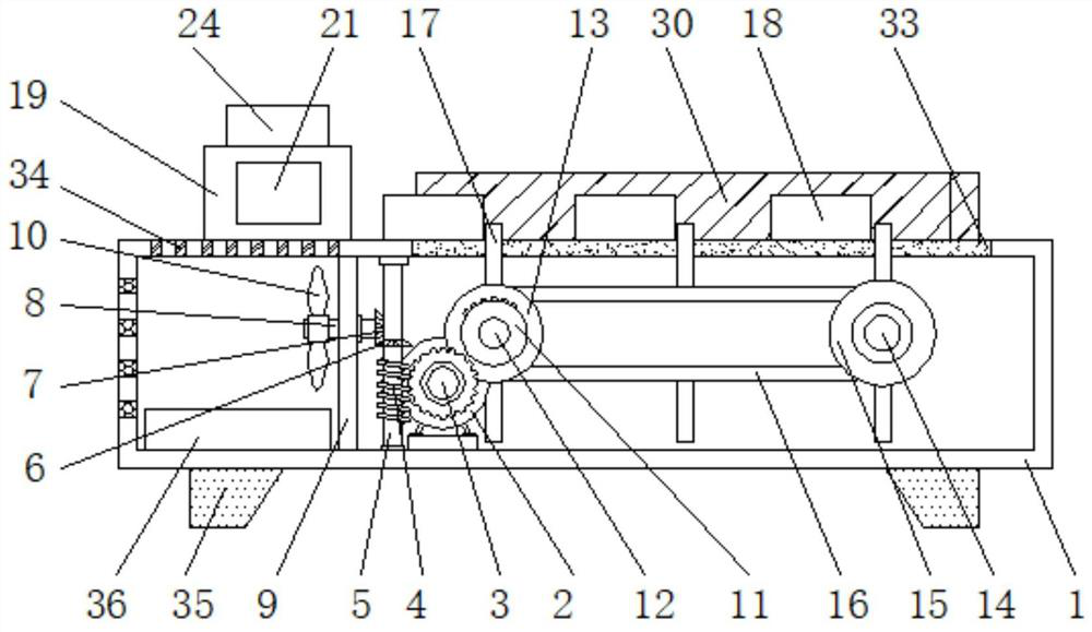
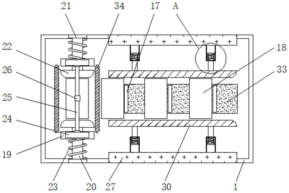
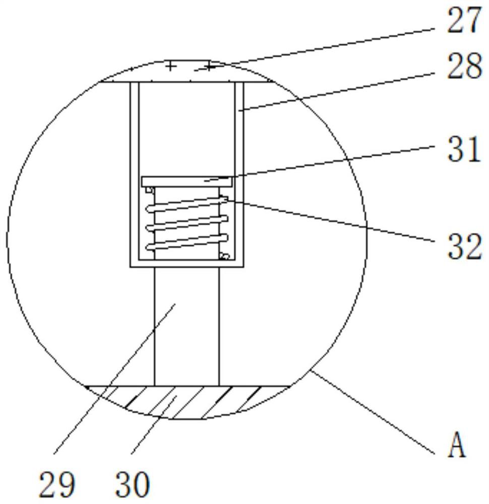
[0023] see Figure 1-3, a hole-drilling device based on chip manufacturing, comprising a body 1, the top of the body 1 is smooth and does not affect the delivery of the workpiece 18, a cooling box 36 is placed at the bottom of the inner cavity of the body 1, and the width of the cooling box 36 is the same as that of the body 1. The distance between the inner wall on the left side and the partition plate 9 is compatible. Cooling liquid is placed in the cooling ...


PUM


Abstract

The invention relates to the technical field of chip processing equipment, and discloses a hole-forming device based on chip manufacturing. The hole-forming device comprises a machine body, a motor isfixedly mounted on the bottom of an inner cavity of the machine body, an output shaft of the motor is fixedly connected with a first mother gear, the left end of the first mother gear is connected with a worm in an engaged manner, a vertical rod is fixedly sleeved with the interior of the worm, the two ends of the vertical rod are movably connected with the top and the bottom of the inner cavityof the machine body, the outer surface of the vertical rod is fixedly sleeved with a second mother gear located above the worm, and the left end of the second mother gear is connected with a second son gear in an engaged manner. According to the hole-forming device based on chip manufacturing, a workpiece is pushed between two fixing blocks through a baffle, the workpiece presses the fixing blocksto enable fixed springs to deform, fixing rods push the fixing blocks to fix the workpiece under the action force of the fixing springs, automatic fixing of the workpiece is achieved, the time for fixing the workpiece is greatly shortened, and the hole-forming speed of the hole-forming device is increased.

Description

technical field [0001] The invention relates to the technical field of chip processing equipment, in particular to a hole opening device for chip manufacturing. Background technique [0002] A chip, also known as an integrated circuit, is a circuit module that integrates a variety of electronic components on a silicon board to achieve a specific function. It is the most important part of electronic equipment and undertakes the functions of computing and storage. To allow the chip to play its unique functions, the chip is drilled with a hole-drilling device. Since the material of the chip is soft, fragile and easily deformed, problems such as non-straight holes, uneven hole diameters, and debris residues often occur when punching holes. [0003] In view of the above-mentioned problems, the existing publication number CN201620897257.6 provides a hand-held microfluidic chip puncher, which can punch holes in the chip by manual hand-holding, the operation is simple and labor-savi...

Claims


Application Information

Patent Timeline
Patent Type & Authority Patents(China)
IPC IPC(8): B23Q3/06B23Q7/00B23Q7/06B23Q11/00B23Q11/12
CPCB23Q3/067B23Q7/003B23Q7/06B23Q11/0042B23Q11/12
Inventor 不公告发明人
Owner ZAOZHUANG HANQI COMM TECH CO LTD
Why Eureka
Try Eureka