Tunnel excavation construction method
A technology of tunnel excavation and construction method, which is applied to tunnels, tunnel linings, shaft linings, etc. It can solve problems such as large headroom, small working face, and restrictions on construction progress, and achieve the effects of ensuring safety, good support, and increasing the speed of entering the tunnel
- Summary
- Abstract
- Description
- Claims
- Application Information
AI Technical Summary
Problems solved by technology
Method used
Image

Examples
Embodiment 1
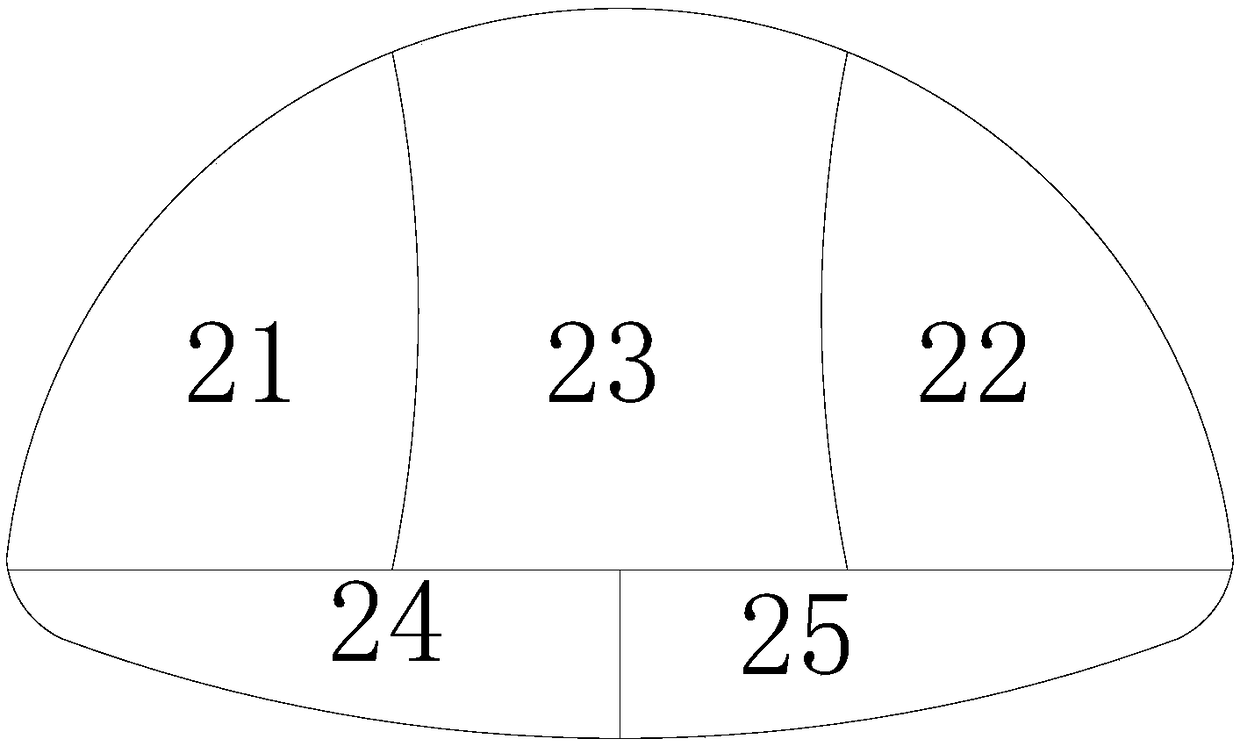
[0049] like Figure 2-8 Shown, a kind of tunnel excavation method of the present invention comprises the following steps:
[0050] (1) The planned tunnel section is divided into five independent excavation units, which are the first unit 21 on the upper left, the second unit 22 on the upper right, the third unit 23 between the first unit 21 and the second unit 22, and the lower left unit The fourth unit 24 and the fifth unit 25 on the lower right, the first unit 21 and the second unit 22 are separated by the third unit 23 at least in the lower part.
[0051] In this embodiment, specifically, such as figure 2 As shown, the first unit 21 and the second unit 22 are completely separated by the third unit 23 .
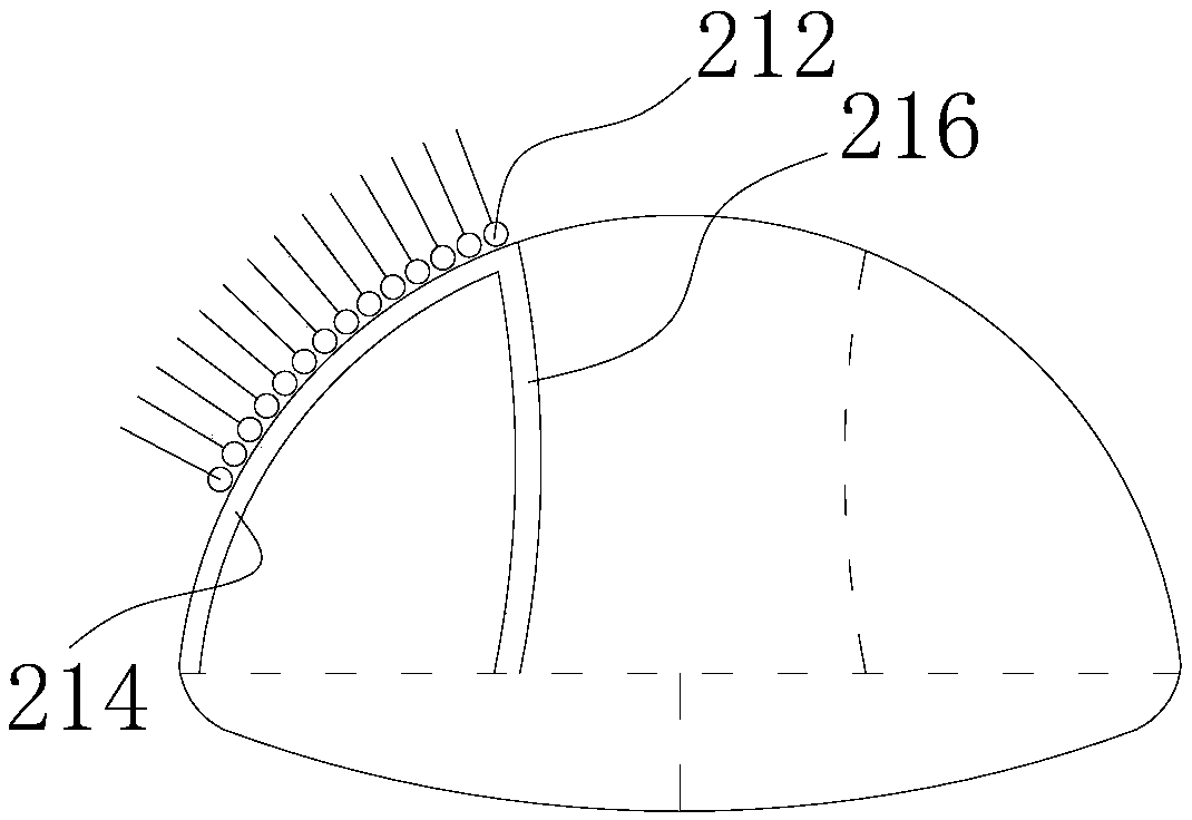
[0052] (2) if image 3 As shown, advance support 212 is performed on the first unit 21, and then excavated, and then the first initial support 214 on the outside of the first unit 21 and the first temporary support 216 on the inside are installed.
[0053] (3) if Fig...
Embodiment 2
[0062] A kind of tunnel excavation method of the present embodiment, and the difference of embodiment 1 is: as Figure 9 As shown, the third unit 23 is subdivided into an upper unit 231 and a lower unit 233 . During construction, in step (4), the upper unit 231 is excavated first, and then the lower unit 233 is excavated.
[0063] Specifically, when constructing the upper unit 231, such as Figure 10 As shown, advance support 232 is performed first, and then excavation is performed, and then the third initial support 234 on the upper side of the upper unit 231 and the third temporary support 236 on the lower side are set.
[0064] More specifically, the third temporary support 236 is bent upwards, and the included angle γ with the horizontal direction is 25°-35°.
[0065] Such as Figure 11 As shown, the lower unit 233 of the third unit 23 is excavated at a distance c from the rear upper unit 231, and c=6m-10m.
Embodiment 3
[0067] Such as Figure 12-15 As shown, the tunnel excavation method of this embodiment differs from that of Embodiment 1 in that: the upper parts of the first unit 21 and the second unit 22 are connected together, and only the lower part is separated by the third unit 23 . The top surface of the third unit 23 is bent downwards, the two ends are bent symmetrically, and the included angle β with the horizontal direction is 45°-60°.
[0068] Wherein step (2) carries out advance support 212 to the first unit 21, and then excavates, and then sets the first initial support 214 on the outside of the first unit 21 and the first temporary support 216 on the inside, as Figure 13 shown. Step (3) Carry out advanced support 222 on the second unit 22, and then excavate, and then set the second initial support 224 on the outside of the second unit 22 and the second temporary support 226 on the inside, as Figure 14 shown. In step (4), only the third unit 23 needs to be excavated.
[006...
PUM
 Abstract
Description
Claims
Application Information
 - R&D
- Intellectual Property
- Life Sciences
- Materials
- Tech Scout
- Unparalleled Data Quality
- Higher Quality Content
- 60% Fewer Hallucinations
Browse by: Latest US Patents, China's latest patents, Technical Efficacy Thesaurus, Application Domain, Technology Topic, Popular Technical Reports.
© 2025 PatSnap. All rights reserved.Legal|Privacy policy|Modern Slavery Act Transparency Statement|Sitemap|About US| Contact US: help@patsnap.com