Eureka AIR delivers breakthrough ideas for toughest innovation challenges, trusted by R&D personnel around the world.

Automobile electronic rearview mirror

A technology for automotive electronics and rearview mirrors, applied in the field of automotive rearview mirrors, can solve problems such as poor visual effects, and achieve the effects of reduced response time, good anti-glare effect, and a wide range of applications

Pending Publication Date: 2019-01-29
HUIZHOU DESAY SV AUTOMOTIVE
View PDF0 Cites 5 Cited by
  • Summary
  • Abstract
  • Description
  • Claims
  • Application Information

AI Technical Summary

Problems solved by technology

[0004] However, this technical solution has several limitations:
Another limitation is that the maximum reflectivity and transmittance of the mirror are both in the undriven state, so when the display function is applied (that is, the transmittance is high), the reflector function is also strong (the reflectivity is large), The two functions affect each other, and the visual effect becomes worse

Method used


Image

  • Automobile electronic rearview mirror
  • Automobile electronic rearview mirror
  • Automobile electronic rearview mirror

Examples


Embodiment 1

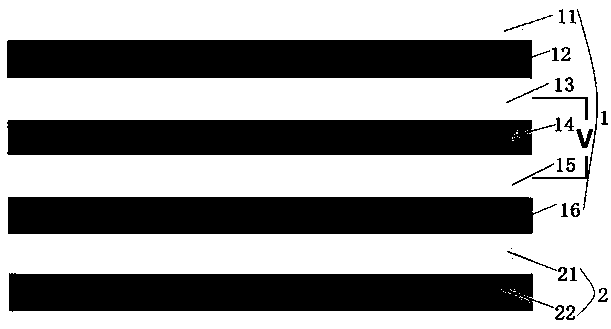
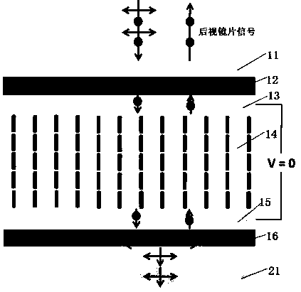
[0047] A kind of automobile electronic rearview mirror, comprises rearview mirror casing, the rearview lens 1 that is arranged on the rearview mirror casing and the liquid crystal display screen 2 that is arranged on rearview lens 1 back side, as figure 1 Shown: rearview lens 1 comprises glass cover plate 11, front glass substrate 13 and rear glass substrate 15, is provided with liquid crystal layer 14 between front glass substrate 13 and rear glass substrate 15, between front glass substrate 13 and rear glass substrate The outer sides of 15 are provided with front polarizer 12 and rear reflective polarizer 16 respectively, and glass cover plate 11 is arranged on the outer side of front polarizer 12; layer, the liquid crystal layer 14 is located between the liquid crystal alignment layer of the front glass substrate 13 and the rear glass substrate 15; the liquid crystal display 2 includes the front polarizer 21 of the liquid crystal display, the light source 22 of the liquid cr...

Embodiment 2

[0060] The difference between this embodiment and Embodiment 1 lies in that the alignment modes of the liquid crystal molecules in the liquid crystal layer 14 are different.

[0061] In this embodiment, the arrangement mode of the liquid crystal molecules of the liquid crystal layer 14 includes a horizontal alignment mode, and the horizontal alignment mode refers to that in the initial state, the positive liquid crystal molecules in the liquid crystal molecules of the liquid crystal layer 14 are all nearly parallel to the front glass substrate 13 and the rear glass substrate 15 are arranged, that is, the negative liquid crystal molecules in the liquid crystal molecules are arranged at an angle of 0.5° to 2° or -0.5° to -2° with the front glass substrate 13 and the rear glass substrate 15 . Under the effect of the liquid crystal alignment layers of the front glass substrate 13 and the rear glass substrate 15, the projection directions of the positive liquid crystal molecules on ...

Embodiment 3

[0067] The difference between this embodiment and Embodiment 1 lies in that the alignment modes of the liquid crystal molecules in the liquid crystal layer 14 are different.

[0068] In this embodiment, the alignment mode of the liquid crystal molecules of the liquid crystal layer 14 includes a conventional twisted orientation mode, and the conventional twisted orientation mode refers to that in the initial state, the positive liquid crystal molecules in the liquid crystal molecules of the liquid crystal layer 14 are on the front glass substrate 13 and the rear glass substrate 15 are twisted and arranged at 90 degrees or -90 degrees. The projection of the positive liquid crystal molecules on the plane of the front glass substrate 13 forms an angle of 0 degree, 90 degree or -90 degree with the front polarizer 12 . In this mode, the optical path difference range of the liquid crystal layer 14 is 375nm≤∆nd≤575nm or 900nm≤∆nd≤1200nm. In this embodiment, the central value of the o...


PUM


Abstract

The invention relates to an automobile electronic rearview mirror. The automobile electronic rearview mirror comprises a rearview mirror shell, a rearview lens arranged on the rearview mirror shell, and a liquid crystal display screen arranged at the back of the rearview lens, wherein the rearview lens comprises a front glass substrate and a rear glass substrate, a liquid crystal layer is arrangedbetween the front glass substrate and the rear glass substrate, a front polarizer and a retroreflective polarizer are respectively arranged outside the front glass substrate and the rear glass substrate, liquid crystal orientation layers are respectively arranged on opposite sides of the front glass substrate and the rear glass substrate, the liquid crystal layer is between the liquid crystal orientation layers of the front glass substrate and the rear glass substrate, the liquid crystal display screen comprises a liquid crystal display screen front polarizer, and the liquid crystal display screen front polarizer is arranged outside the retroreflective polarizer. Due to use of the front polarizer, the liquid crystal layer and the retroreflective polarizer, reflected light strength of therearview lens and transmitted light strength of the liquid crystal display screen are controlled through bias voltage applied to the liquid crystal layer.

Description

technical field [0001] The invention relates to the technical field of automobile rearview mirrors, in particular to an automobile electronic rearview mirror. Background technique [0002] With the increasing safety, comfort and intelligence of automotive products, automotive electronic rearview mirrors have gradually added automatic anti-glare functions and display functions. Generally speaking, the rearview mirror that adds these two functions contains a liquid crystal display screen and an automatic anti-glare rearview mirror installed at its front end. [0003] At this stage, the automatic anti-glare rearview mirror adopts the electrochromic technical solution. The rearview mirror has a light-absorbing effect due to the color change of the electrochromic solution, and the reflectivity will decrease with the bias voltage to play the role of anti-glare. When the reflectivity of the automatic anti-glare rearview mirror is the highest, its transmittance is also the highest...

Claims


Application Information

Patent Timeline
Patent Type & Authority Applications(China)
IPC IPC(8): G02F1/139G02F1/1335B60R1/08B60R1/12
CPCG02F1/133528G02F1/139B60R1/088B60R1/12B60R2001/1215
Inventor 郭建新
Owner HUIZHOU DESAY SV AUTOMOTIVE
Why Eureka
Eureka Blog
Learn More