Vehicle collision detection method and vehicle control system
A technology of a vehicle control system and a detection method, which is applied to control devices, vehicle components, vehicle safety arrangements, etc., can solve problems such as misjudgments as collision accidents, and achieve the effects of eliminating misjudgments, improving accuracy, and reducing misjudgments
- Summary
- Abstract
- Description
- Claims
- Application Information
AI Technical Summary
Problems solved by technology
Method used
Image
Examples
Embodiment 1
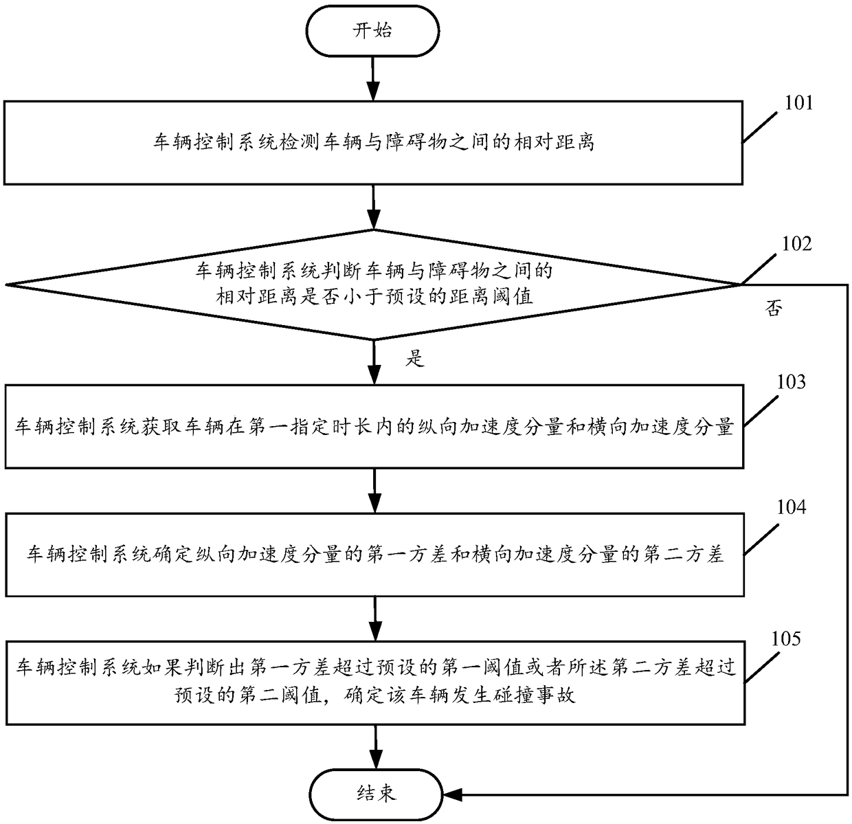
[0062] see figure 1 , figure 1 It is a schematic flowchart of a vehicle collision detection method disclosed in an embodiment of the present invention. Such as figure 1 As shown, the vehicle collision detection method may include the following steps:
[0063] 101. The vehicle control system detects the relative distance between the vehicle and the obstacle.
[0064] In the embodiment of the present invention, the vehicle control system can specifically detect the relative distance between the vehicle and the obstacle through the measurement data of the ranging sensor and / or the camera. Wherein, the ranging sensor may be an ultrasonic ranging sensor, a laser ranging sensor, an infrared ranging sensor, a microwave ranging sensor, etc., which are not limited in this embodiment of the present invention. When the vehicle control system detects the relative distance between the vehicle and the obstacle through the ranging sensor, the distance data fed back by the ranging sensor ...
Embodiment 2
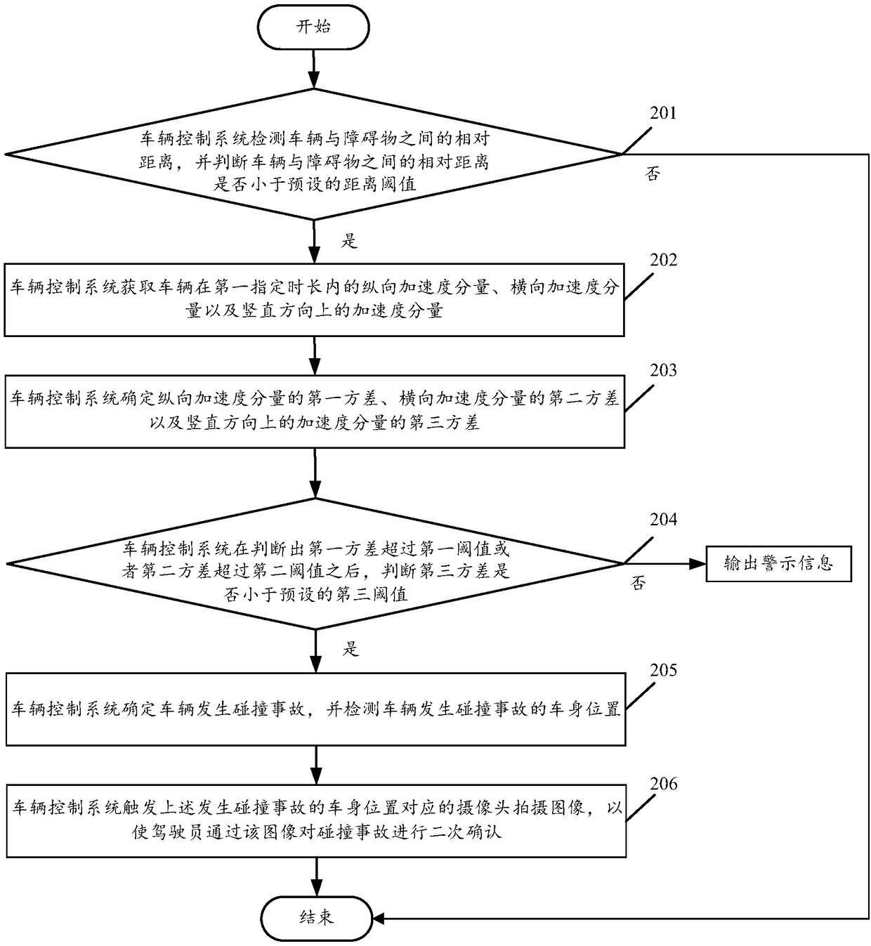
[0076] see figure 2 , figure 2 It is a schematic flowchart of another vehicle collision detection method disclosed in the embodiment of the present invention. Such as figure 2 As shown, the vehicle collision detection method may include the following steps:
[0077] 201. The vehicle control system detects the relative distance between the vehicle and the obstacle, and judges whether the relative distance is smaller than a preset distance threshold. If yes, execute step 202. If not, end the process.
[0078] 202. The vehicle control system acquires a longitudinal acceleration component, a lateral acceleration component, and a vertical acceleration component of the vehicle within a first specified time period.
[0079] In the embodiment of the present invention, it can be specifically obtained through the measurement data of the three-axis accelerometer installed on the vehicle. The three-axis accelerometer can obtain the X-axis (longitudinal), Y-axis (horizontal) and Z-ax...
Embodiment 3
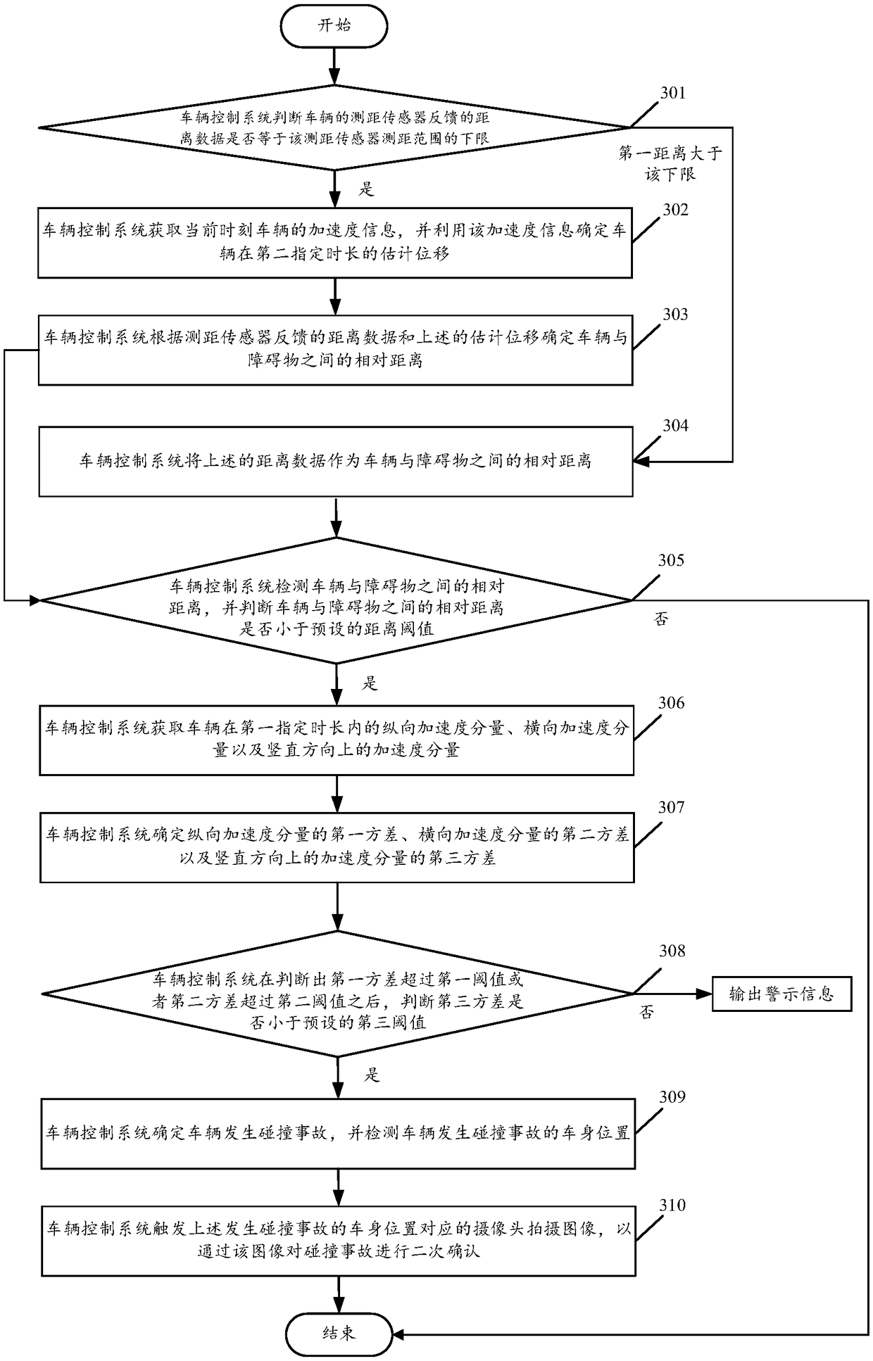
[0090] see image 3 , image 3 It is another vehicle collision detection method disclosed in the embodiment of the present invention. Such as image 3 As shown, the vehicle collision detection method may include the following steps:
[0091] 301. The vehicle control system judges whether the distance data fed back by the ranging sensor of the vehicle is equal to the lower limit of the ranging range of the ranging sensor. If yes, execute steps 302 to 303. If not and the first distance is greater than the lower limit of the ranging range, Execute step 304 .
[0092] In the embodiment of the present invention, taking the ultrasonic ranging sensor as an example, the lower limit of the ranging range of some ultrasonic sensors is 26cm (according to the difference in sensor performance, the specific value of the lower limit of the ranging range is different), when the distance between the vehicle and the obstacle When the actual distance is less than 26cm, the distance data retur...
PUM
 Abstract
Description
Claims
Application Information
 - Generate Ideas
- Intellectual Property
- Life Sciences
- Materials
- Tech Scout
- Unparalleled Data Quality
- Higher Quality Content
- 60% Fewer Hallucinations
Browse by: Latest US Patents, China's latest patents, Technical Efficacy Thesaurus, Application Domain, Technology Topic, Popular Technical Reports.
© 2025 PatSnap. All rights reserved.Legal|Privacy policy|Modern Slavery Act Transparency Statement|Sitemap|About US| Contact US: help@patsnap.com


