
Imaging model construction method and calibration method of linear array rotary scanning camera based on projection transformation

A technology of rotational scanning and projection transformation, applied in image analysis, 3D modeling, image data processing, etc., can solve the problems that rotational scanning linear array images are not suitable for 3D reconstruction, the accuracy of calibration results is not high, and the imaging model parameters are too many. To achieve the effect of 3D reconstruction, simple and flexible method, and easy construction

Active Publication Date: 2019-01-25
WUHAN UNIV
View PDF7 Cites 9 Cited by
  • Summary
  • Abstract
  • Description
  • Claims
  • Application Information

AI Technical Summary

Problems solved by technology

[0006] The main purpose of the present invention is to propose a method for constructing an imaging model of a rotating scanning line array camera and a calibration method suitable for three-dimensional reconstruction, so as to solve the problem that the existing imaging model of a rotating scanning line array camera has many parameters, the solution is complicated and the accuracy of the calibration result is not accurate. Therefore, it solves the problem that the rotating scanning line array image is not suitable for three-dimensional reconstruction, thereby broadening the application field of the rotating scanning line array image

Method used


Image

  • Imaging model construction method and calibration method of linear array rotary scanning camera based on projection transformation
  • Imaging model construction method and calibration method of linear array rotary scanning camera based on projection transformation
  • Imaging model construction method and calibration method of linear array rotary scanning camera based on projection transformation

Examples


Embodiment 1

[0109] The line array imaging camera is combined with the rotating scanning platform to collect images in the three-dimensional control field of close-range photogrammetry, and the line array imaging camera is calibrated by using the control points.

[0110] Table 1 is the parameter setting when the camera shoots

[0111] Scanning angle / deg

Integration time / ms

Rotation speed / deg / s

Scan lines per second

53

200

0.177

5.04

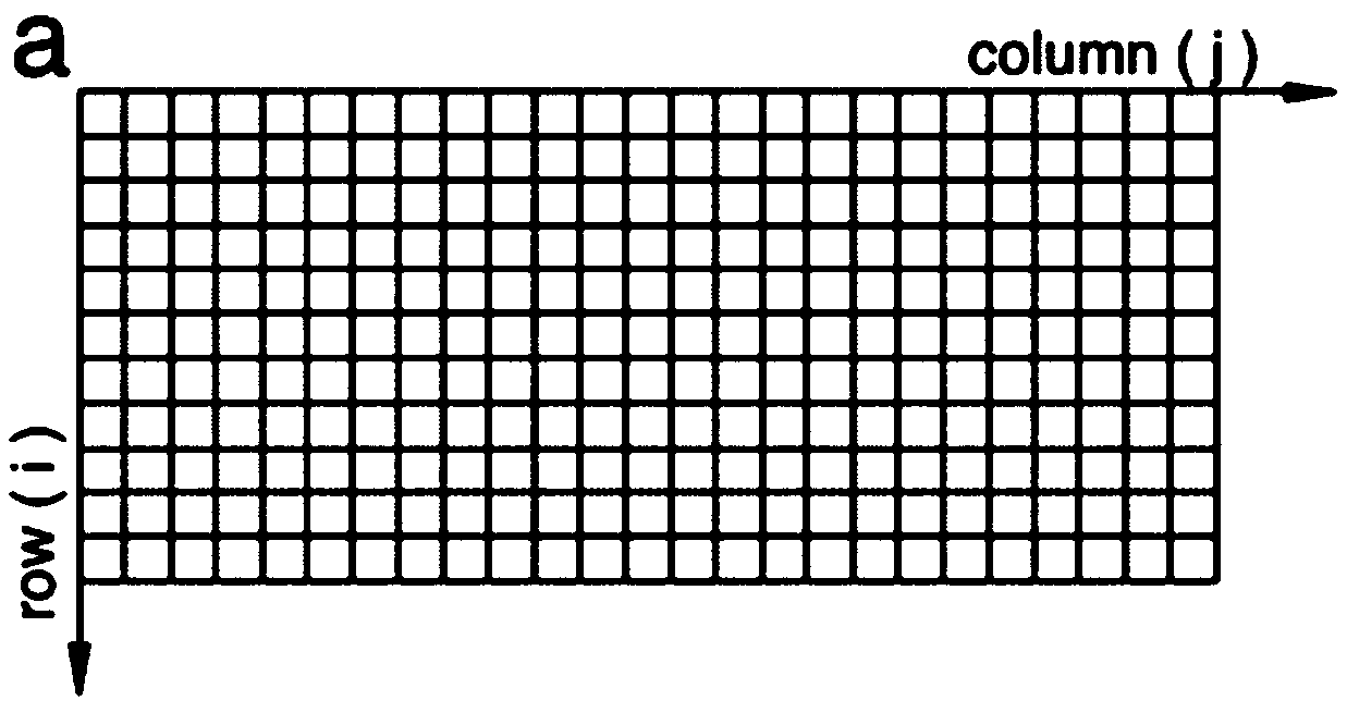
[0112] Figure 4 For the collected close-range photogrammetry 3D control field image, the coordinates of control points in the image can be extracted automatically by using computer vision methods, or by manually extracting marker points to extract image marker points. A total of 53 marker points were extracted.

[0113] Take the rotation angle α set when the camera is shooting as the true value, and use the image point coordinate calculation formula of the virtual frame image after projection transformation to calcu...


PUM


Abstract

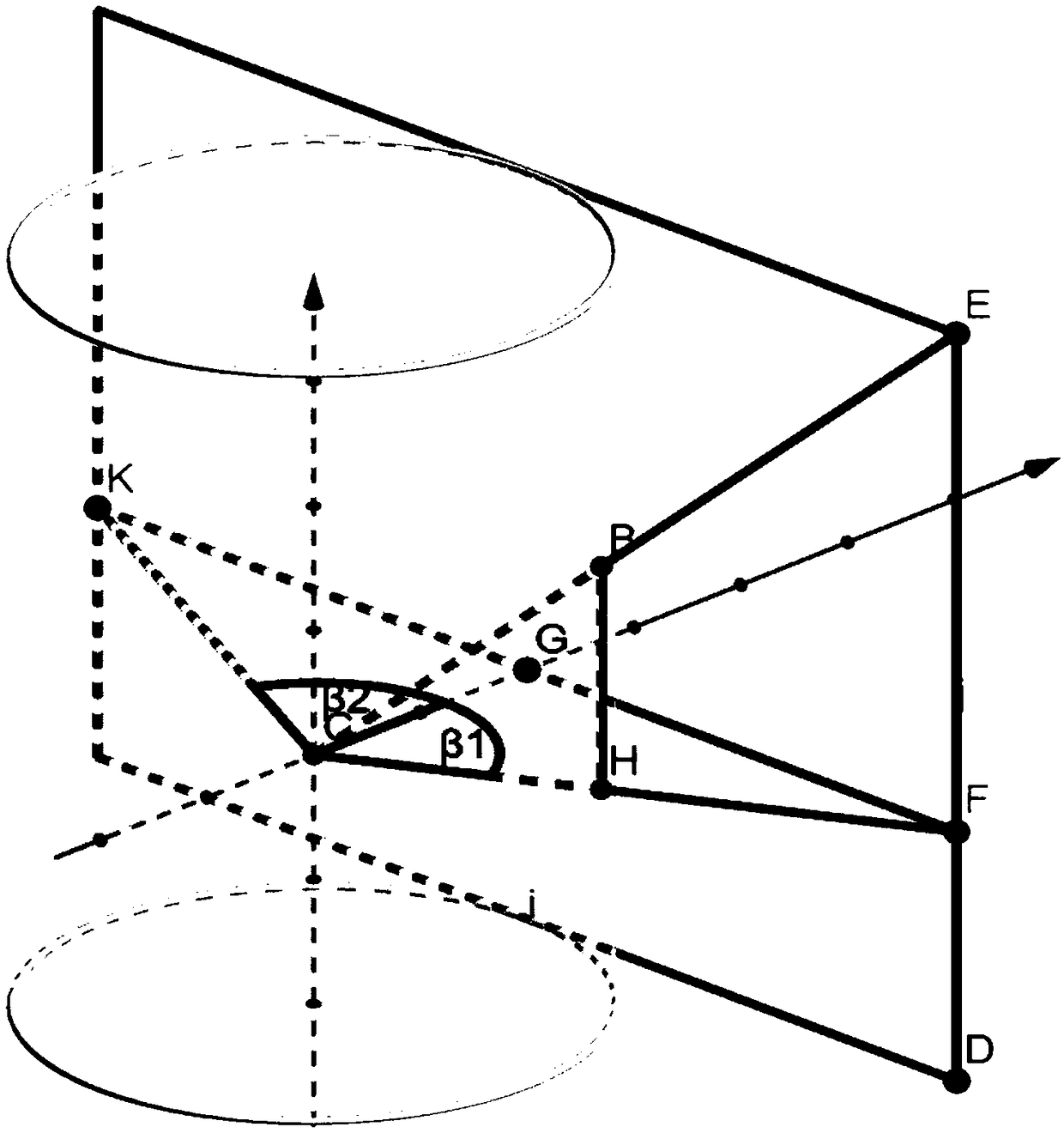
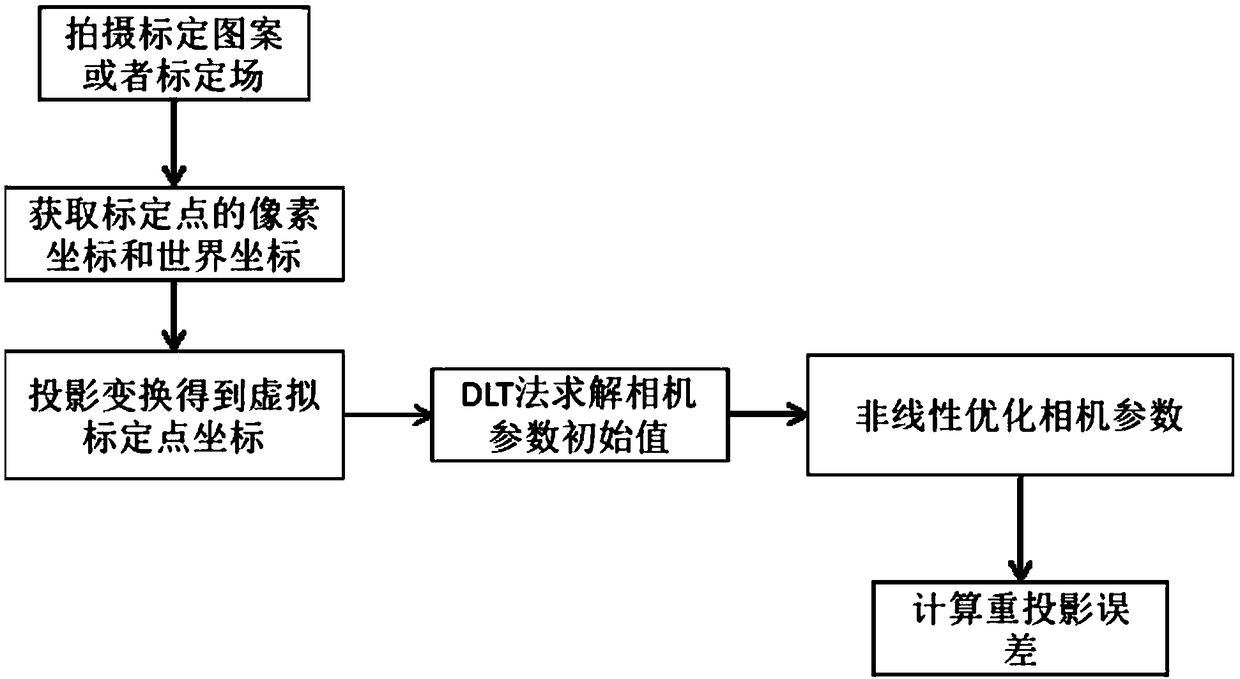
The invention provides an imaging model construction method and a calibration method of a linear array rotary scanning camera based on projection transformation, the method comprises that follow steps: based on the imaging principles of linear array rotary scanning camera and frame camera, camera rotation platform parameter, the geometrical relationship between the coordinates of the image pointson the original imaging plane of the linear array rotary scanning camera and the coordinates of the corresponding image points on the virtual frame image with the tangent plane as the imaging plane isdetermined by the positional relationship between the imaging plane of the linear array rotary scanning camera and its tangent plane, so as to determine a new imaging model of the linear array rotaryscanning camera. The calibration method comprises the following steps of: calibrating a linear array rotary scanning camera by using the imaging model, adopting a direct linear transformation methodand a non-linear optimization method according to the obtained control points and corresponding image point coordinates. Compared with the traditional method, the method of the invention is simple andfast, and has higher precision. It is easier to construct nuclear images, so it is more suitable for three-dimensional reconstruction.

Description

technical field [0001] The invention relates to the technical field of close-range photogrammetry, in particular to a construction method and a calibration method for an imaging model of a linear array rotary scanning camera based on projection transformation. Background technique [0002] The linear scan camera is a non-traditional one-dimensional imaging device, which is widely used in the fields of industrial inspection and satellite imaging. Line scan cameras generally have a higher sampling rate and spatial resolution than frame and frame cameras. Line scan cameras have better performance in many close-range photography applications, such as 3D scene reconstruction, pose measurement of high-speed objects. In these applications, camera geometry calibration is an essential step in order to obtain accurate metrology information of linear array images. [0003] The dynamic camera geometric calibration method based on the rotating motion platform, so far, there are relativ...

Claims


Application Information

Patent Timeline
IPC IPC(8): G06T17/00G06T7/80
CPCG06T7/80G06T17/00
Inventor 巫兆聪闫钊苏琳王鹏
Owner WUHAN UNIV
Learn More