Low-heating-value gas burner and hot blast heater

A gas burner and low calorific value technology, applied in the direction of burners, combustion methods, combustion types, etc., can solve the problems of low combustion efficiency, high investment, large size requirements, etc., achieve high combustion efficiency, reduce investment, and wide adjustment range Effect

Pending Publication Date: 2019-01-25
ZHONGYE-CHANGTIAN INT ENG CO LTD
View PDF0 Cites 4 Cited by
  • Summary
  • Abstract
  • Description
  • Claims
  • Application Information

AI Technical Summary

Problems solved by technology

[0006] The purpose of the present invention is to provide a low calorific value gas burner and hot blast stove, which solves the technical problems of large size requirements, high investment and low combustion efficiency in existing hot blast stoves

Method used


Image

  • Low-heating-value gas burner and hot blast heater
  • Low-heating-value gas burner and hot blast heater
  • Low-heating-value gas burner and hot blast heater

Examples


Embodiment 1

[0037] The embodiment of the present invention provides a low-calorific-value gas burner that uses low-calorific-value gas as fuel and has a large heating capacity. Large and difficult to operate and adjust. The low calorific value gas burner will be described in detail below.

[0038] Such as Figure 5-8As shown, the low calorific value gas burner described in the embodiment of the present invention includes an external main burner and an internal auxiliary burner, wherein the external main burner includes an external distribution pipe 1, a A plurality of first gas pipelines 2 and a plurality of first nozzles 3 connected to the first gas pipelines 2 in one-to-one correspondence, on which first nozzles 3 are installed a first mixing nozzle 4 . The internal auxiliary burner includes an internal distribution pipe 5, a plurality of second gas pipelines 6 arranged in the internal distribution pipe 5, and a plurality of second nozzles 7 connected to the second gas pipelines 6 in ...

Embodiment 2

[0050] The embodiment of the present invention provides a hot blast stove that uses low-calorific-value gas as fuel and has a large heating capacity to solve the problems of large volume, high investment and low heat utilization efficiency when using low-calorific-value gas as fuel in the existing hot-blast stove. The hot blast stove will be described in detail below.

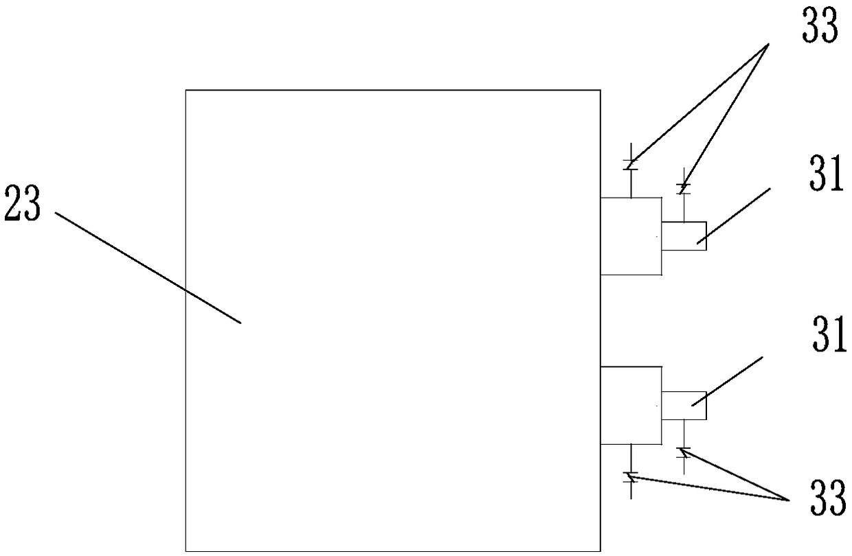
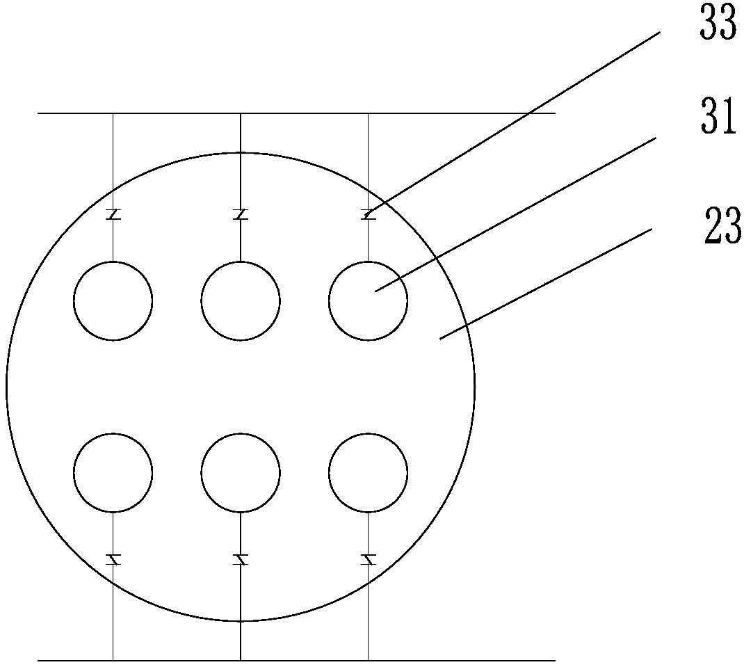
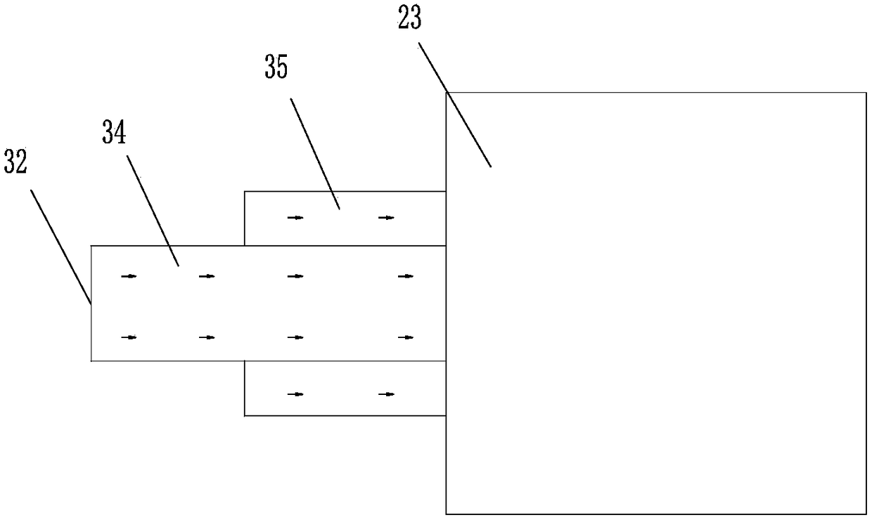
[0051] Such as Figure 9 As shown, on the basis of the first embodiment above, the embodiment of the present invention also provides a hot blast stove, including a hot blast stove body 21 and a burner 22 arranged on the hot blast stove body, wherein the burner 22 is the above-mentioned low calorific value gas burners.

[0052] Wherein, the hot blast stove body includes a combustion chamber 23 and an air mixing chamber 24, and a partition wall 25 is arranged between the combustion chamber 23 and the air mixing chamber 24, and the partition wall 25 is built by interlacing refractory bricks. As a result, the par...


PUM


Abstract

The invention relates to the technical field of hot blast heaters, in particular to a low-heating-value gas burner and a hot blast heater. The low-heating-value gas burner comprises an external main burner and an internal auxiliary burner; the external main burner comprises an outer distribution tube, a plurality of first gas pipelines and a plurality of first nozzles, wherein the first gas pipelines are arranged in the outer distribution tube, and the first nozzles are correspondingly connected to the first gas pipelines one to one; the internal auxiliary burner comprises an inner distribution tube, a plurality of second gas pipelines and a plurality of second nozzles, wherein the second gas pipelines are arranged in the inner distribution tube, and the second nozzles are correspondinglyconnected to the second gas pipelines one to one. The low-heating-value gas burner and the hot blast heater have the advantages that the structure is reasonable, the size is moderate, the low-heating-value gas burner is suitable for the hot blast heater with large water content and high heat supply capacity requirements, especially when low-heating-value gas is used, the heating supply problem ofthe whole hot blast heater can be completely solved by using a single burner, the adjustment range is wide, the combustion efficiency is high, the energy consumption is reduced, the volume of the hotblast heater can be reduced accordingly, and the investment is reduced.

Description

technical field [0001] The invention relates to the technical field of hot blast stoves, in particular to a low calorific value gas burner and a hot blast stove. Background technique [0002] Hot blast stove is a kind of equipment widely used in industrial production at present. It produces low-oxygen hot flue gas through combustion, which can be used as inert gas to treat some materials. The raw materials mainly include coal powder and gas. In terms of gas, there are various raw materials such as natural gas, coal gas, and liquefied petroleum gas. In industrial production, some combustible gases with low calorific value are often by-produced, such as blast furnace gas, converter gas, etc. Under the current development trend of energy saving and emission reduction, how to effectively use these combustible gases with low calorific value is an issue for the entire industry. matter of great concern. [0003] In the existing dry hot stove system, if its heating capacity exceed...

Claims


Application Information

Patent Timeline
Patent Type & Authority Applications(China)
IPC IPC(8): F23D14/02F23D14/58F23D14/62
CPCF23D14/02F23D14/58F23D14/62F23D2900/14002F23D2900/14003F23D2900/14021F23D2900/21001
Inventor 何森棋李文辉
Owner ZHONGYE-CHANGTIAN INT ENG CO LTD
Why Eureka
Try Eureka