
Support jig used for laptop part manufacturing

A part processing and notebook technology, applied in the field of support fixtures, can solve the problems of unable to complete the reliable clamping of parts, unable to reliably support the support points, etc., to save the processing process, simple structure, strengthen the shrinkage force and the stability of the structure Effect

Pending Publication Date: 2019-01-25
苏州丰川电子科技有限公司
View PDF0 Cites 0 Cited by
  • Summary
  • Abstract
  • Description
  • Claims
  • Application Information

AI Technical Summary

Problems solved by technology

[0003] As we all know, during the machining process of parts, such as the processing of the side cover of the notebook computer, the parts need to be supported and positioned by the jig, but during the processing of the parts, due to the processing error or the height of the supporting surface itself is different, so During the clamping process of the existing fixture, there may be a certain support point that cannot be reliably supported, and the reliable clamping of the part cannot be completed

Method used


Image

  • Support jig used for laptop part manufacturing
  • Support jig used for laptop part manufacturing
  • Support jig used for laptop part manufacturing

Examples


Embodiment 1

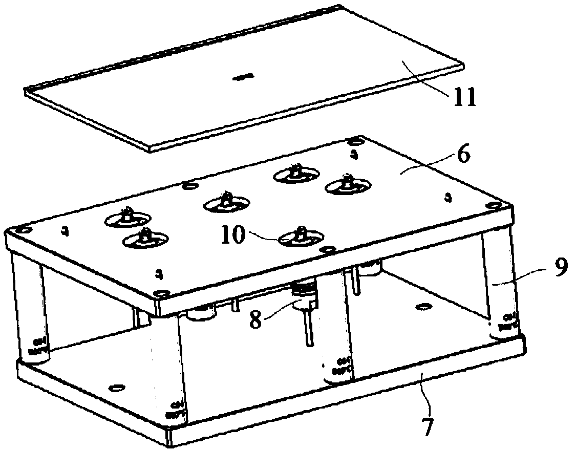
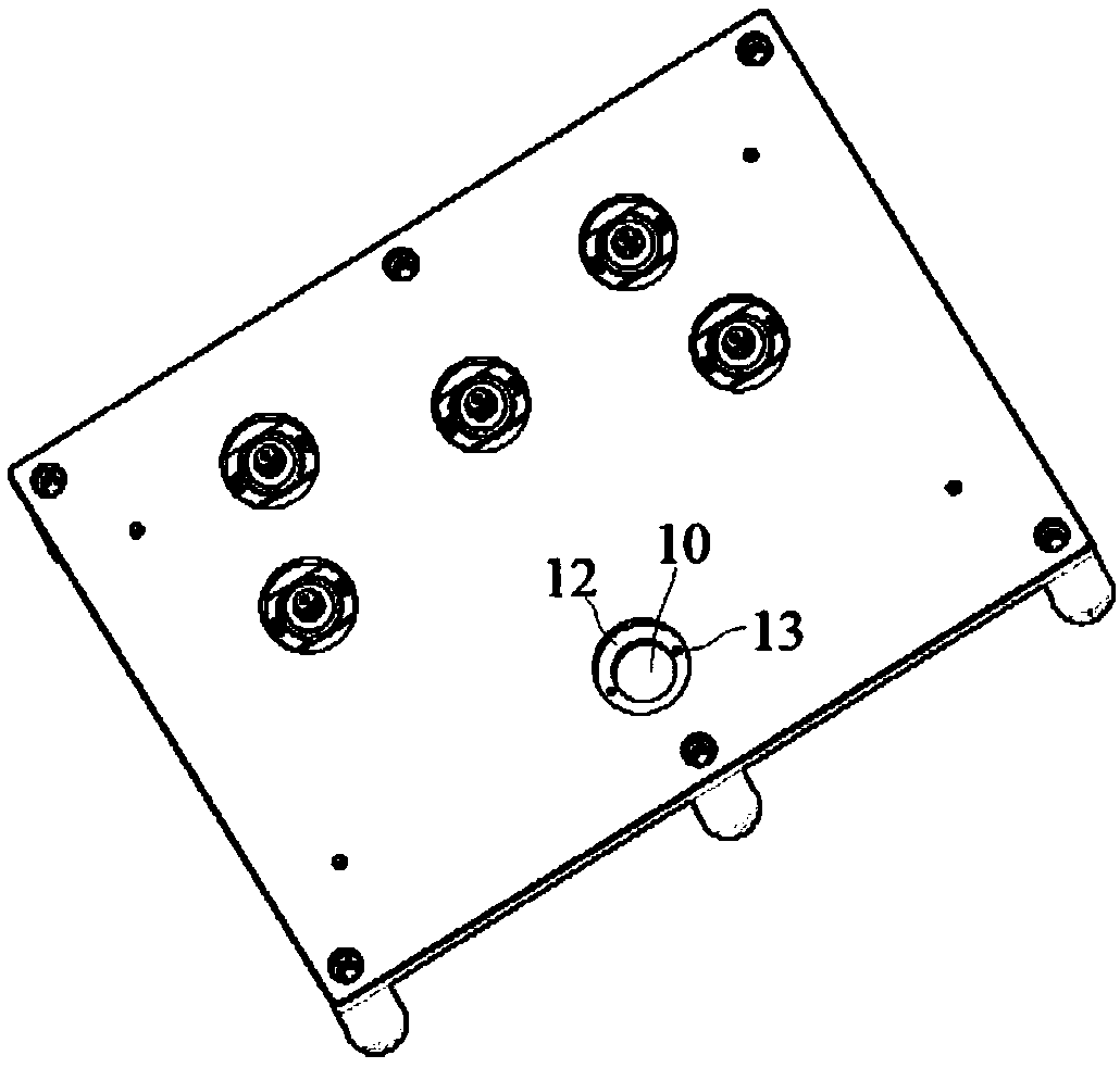
[0034] Embodiment 1: A support jig for processing notebook parts, including a first mounting plate 6, a second mounting plate 7 and several support heads 8 arranged in parallel, the first mounting plate 6 and the second mounting plate 7 Connected by a plurality of supporting columns 9, a plurality of through holes 10 are opened on the first mounting plate 6, and the upper ends of the supporting heads 8 protrude from the through holes 10 respectively and are installed and connected with the first mounting plate 6, and a workpiece 11 is placed above the first mounting plate 6 and connected with the support head 8;

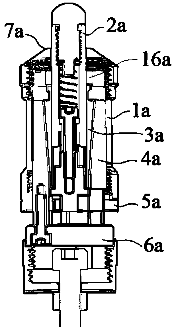
[0035]The support head 8 includes a housing 1a, a movable push rod 2a, an elastic sleeve 3a, a movable sleeve 4a, a bottom cover 5a and a push block 6a, and the bottom cover 5a is connected to the lower end of the housing 1a, so that A cavity is formed between 1a and the bottom cover 5a, a through hole 7a is opened on the top plate of the housing 1a for the movable m...

Embodiment 2

[0042] Embodiment 2: A support jig for processing notebook parts, including a first mounting plate 6, a second mounting plate 7 and several supporting heads 8 arranged in parallel, the first mounting plate 6 and the second mounting plate 7 Connected by a plurality of supporting columns 9, a plurality of through holes 10 are opened on the first mounting plate 6, and the upper ends of the supporting heads 8 protrude from the through holes 10 respectively and are installed and connected with the first mounting plate 6, and a workpiece 11 is placed above the first mounting plate 6 and connected with the support head 8;

[0043] The support head 8 includes a housing 1a, a movable push rod 2a, an elastic sleeve 3a, a movable sleeve 4a, a bottom cover 5a and a push block 6a, and the bottom cover 5a is connected to the lower end of the housing 1a, so that A cavity is formed between 1a and the bottom cover 5a, a through hole 7a is opened on the top plate of the housing 1a for the movab...


PUM


Abstract

The invention discloses a support jig used for laptop part manufacturing. The support jig comprises a first mounting plate, a second mounting plate and a plurality of support heads, the first mountingplate and the second mounting plate are arranged parallelly and connected through a plurality of support columns, and a plurality of through holes are formed in the first mounting plate. For each ofthe support heads, a through hole allowing a movable ejector rod to penetrate through is formed in a top plate of a shell, an ejector head is embedded in a cylinder from an upper side and is fixedly connected with the cylinder, a connection rod is embedded in the cylinder from a lower side and is movably connected with an inner wall of the cylinder, a spring is arranged between the ejector head and the connection rod, an outer surface of an elastic clamping sleeve is a tapered surface, an inner surface of a movable sleeve is a tapered surface, radiuses of tapered surfaces decrease from top tobottom, the outer surface of the elastic clamping sleeve and the inner surface of the movable sleeve are in clearance fit, and a bottom side of a first clamping sleeve is connected with a top side ofa second clamping sleeve. The support jig is capable of realizing support for workpieces with lower bending surfaces and keeping natural being states of the workpieces, and is delicate in structure and simple to operate.

Description

technical field [0001] The invention relates to a supporting fixture used for processing notebook parts, and belongs to the technical field of processing precision parts of electronic products. Background technique [0002] At present, with the continuous emergence of new technologies and materials, product processing tends to be more and more high-precision and good surface finish. Excellent products are an important guarantee for enterprises to improve product added value and competitiveness. [0003] As we all know, during the machining process of parts, such as the processing of the side cover of the notebook computer, the parts need to be supported and positioned by the jig, but during the processing of the parts, due to the processing error or the height of the supporting surface itself is different, so During the clamping process of the existing fixture, a certain support point may not be supported reliably, and the reliable clamping of the parts cannot be completed. ...

Claims


Application Information

Patent Timeline
IPC IPC(8): B25B11/00B23Q3/08
CPCB23Q3/08B25B11/00
Inventor 蒋燕赵长亮周士升詹淳崵
Owner 苏州丰川电子科技有限公司
Learn More