
Traffic sign on luminescent road and lamp bead lens for traffic sign

A technology for road traffic and light-emitting lights, applied in road signs, roads, roads and other directions, can solve the problems of cumbersome installation methods, rising production and installation costs, low work efficiency, etc., to reduce processing costs, reduce processing accuracy requirements, reduce The effect of making installation costs

Pending Publication Date: 2019-01-22
HUNAN XIANGXU TRAFFIC & LIGHTING HI TECH CO LTD
View PDF0 Cites 1 Cited by
  • Summary
  • Abstract
  • Description
  • Claims
  • Application Information

AI Technical Summary

Problems solved by technology

[0003] One is the structural method of the prior art, the installation method is cumbersome, and two different parts need to be installed and matched from the front and rear of the sign at the same time, and they need to be aligned with each other before they can be inserted and installed, resulting in troublesome operation and slow installation efficiency , low work efficiency
[0004] The second is the structure of the prior art. Since it needs to be plugged and unplugged from both sides during operation, the direction of force applied on both sides is uneven, or when the force applied to one side is too large, it is easy to cause the base to burst, and the cost of production and installation increases.
[0005] The third is that the structure of the prior art requires high processing precision for the base and the insertion rod. If the processing is not precise, the insertion rod cannot be inserted into the base, or the base space is too large so that the insertion rod cannot be fixed. Seriously affect the quality of signage products, which in turn has a great impact on traffic safety
[0006] The 4th, this structure mode of prior art, owing to be manual plug-in fit, make there is not an absolute fixed position
The installation strength of the operators is not the same standard, which makes some operators think that the installation is stable at that time. In fact, in the subsequent use of handling, hoisting, etc., it is easy to cause the base and the insertion rod to loosen and separate, which seriously affects the quality of the signage products. , and thus have a great impact on traffic safety
[0007] The fifth is the structural mode of the prior art. This plug-in fit is not firmly installed, and there is a gap between the lens and the sign. The installation hole of the sign penetrates into the interior of the sign, causing damage to the internal electronic components, seriously affecting the quality of the sign product, and thus having a great impact on traffic safety
[0008] Sixth, this structural method of the prior art only sets the clamping structure on the base. When the lamp bead is inserted, it can only clamp the tail of the lamp bead, but there is no restriction on the body of the lamp bead, which causes the lamp bead, especially the lamp holder, to be stuck. The position is not fixed in the insert rod, so that the light emitted by the lamp bead cannot emit light from the best lens part, so that the light emitted by the lens cannot form a uniform light. In terms of signage, the impact is very large

Method used


Image

  • Traffic sign on luminescent road and lamp bead lens for traffic sign
  • Traffic sign on luminescent road and lamp bead lens for traffic sign
  • Traffic sign on luminescent road and lamp bead lens for traffic sign

Examples


Embodiment Construction

[0035] The present invention will be further described in detail below in conjunction with the accompanying drawings and specific embodiments.

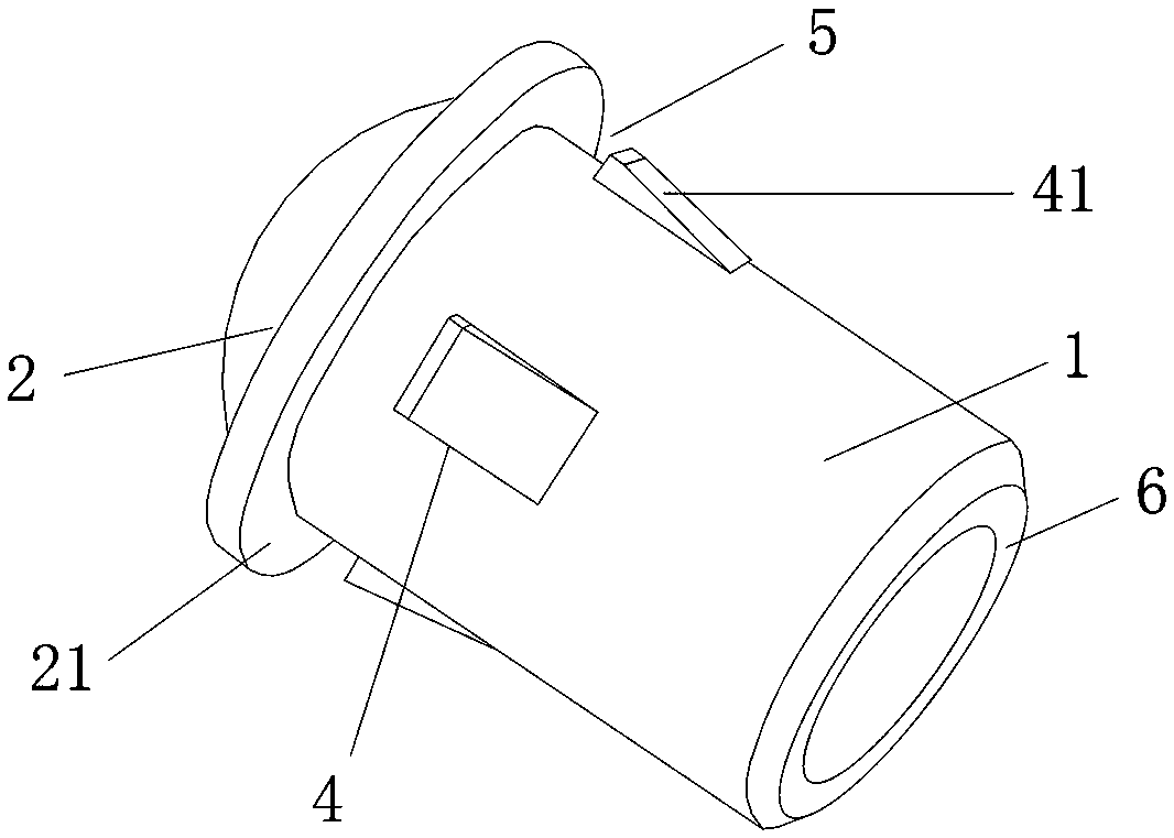
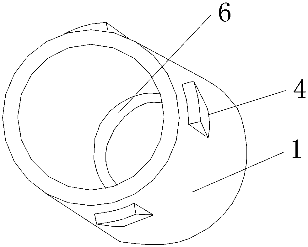
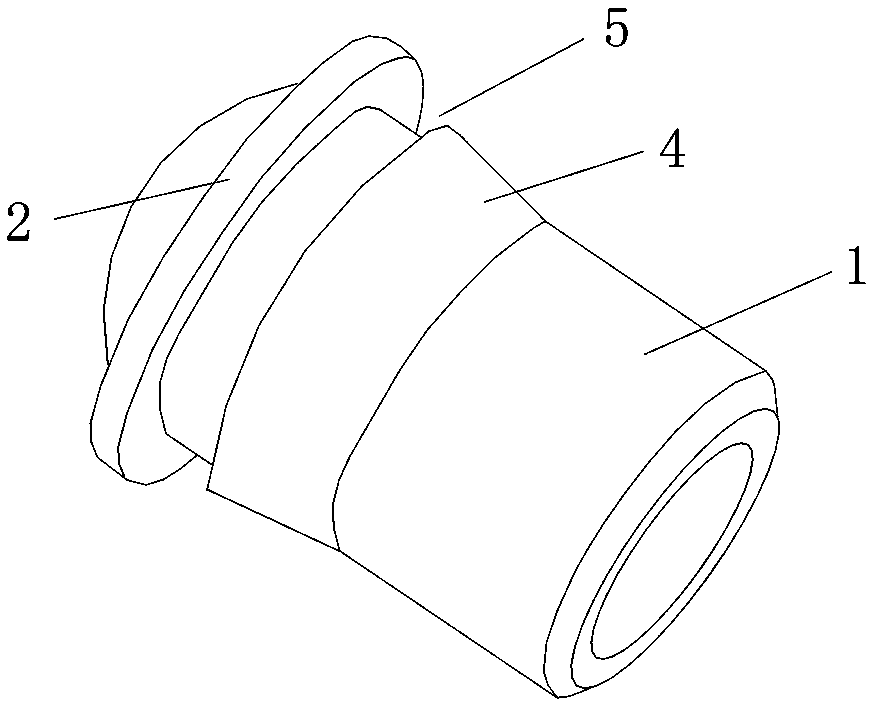
[0036] Such as Figure 1 to Figure 5As shown, the present invention provides a lamp bead lens for luminous road traffic signs, which includes a mounting rod 1 and a lens 2 fixed on the head end of the mounting rod 1. The mounting rod 1 is hollow to allow the luminous lamp bead 3 from The tail end of the installation rod 1 is inserted, the diameter of the lens 2 is greater than the diameter of the installation rod 1, and a circle of protruding guide stopper 4 is provided on the circumferential surface of the installer rod 1 to form a gap between the lens 2 and the guide stopper 4. A circle of clamping space 5, the guide limit part 4 is provided with a guide slope 41 inclined upward towards the direction of the lens 2, during installation, the installation rod 1 is inserted into the installation hole of the traffic sign from the front, ...


PUM


Abstract

The invention discloses a lamp bead lens for a traffic sign on a luminescent road. The lamp bead lens comprises a mounting rod and a lens. The lens is fixed onto the head end of the mounting rod, a luminescent lamp bead can be inserted into the hollow mounting rod from the tail end of the mounting rod, the diameter of the lens is larger than that of the mounting rod, and a circle of protruded guide restraint portions is arranged on the circumferential surface of the mounting rod, so that a circle of clamping space can be formed between the lens and the guide restraint portions; each guide restraint portion is provided with a guide oblique plane which is upwardly oblique towards the direction of the lens; the mounting rod can be inserted into mounting holes of a traffic signboard from the front surface of the traffic signboard during mounting, and the guide oblique planes can be gradually squeezed by the traffic signboard to deform, and then are ultimately fed into the clamping space tobe clamped and restrained. The invention further discloses the traffic sign on the luminescent road. The lamp bead lens and the traffic sign have the advantages of simple and compact structure, convenience and speediness in mounting, low manufacturing cost and high safety.

Description

technical field [0001] The invention mainly relates to the field of road traffic sign manufacturing, in particular to a lamp bead lens for a luminous road traffic sign, and also to a luminous road traffic sign. Background technique [0002] With the development of road traffic, the beautification of roads, and the improvement of traffic safety requirements, there are more and more applications of road traffic luminous signs. There are multiple lenses installed on the traditional traffic luminous sign, and there are lamp beads inside to emit light. The lens structure is divided into two independent parts, one part is the insertion rod with the lens, and the other part is the matching base. When installing, first insert the insertion rod with lens from the front of the sign, and then insert the base into the insertion rod from the back of the sign, so that the insertion rod is inserted into the base to form a plug-in fixation. This has the following technical problems: [0...

Claims


Application Information

Patent Timeline
Patent Type & Authority Applications(China)
IPC IPC(8): F21V5/04E01F9/615
CPCF21V5/04E01F9/615
Inventor 蒋浪易雪峰
Owner HUNAN XIANGXU TRAFFIC & LIGHTING HI TECH CO LTD
Learn More