


Quick Research
Generate reliable direction feasibility study reports for your R&D in just a few steps.

Technical Q&A
Discover and master advanced knowledge NOW. Basics, ideas, possibilities, all at once.

Find Solutions
As an expert in R&D theories, this can generate solutions to your technical problems instantly.

Evaluate Feasibility
Analyze your overall solution with one click, know your potential R&D risks in advance.

Monitor Landscape
Get weekly tech updates, stay abreast of the latest tech innovations and key insights.
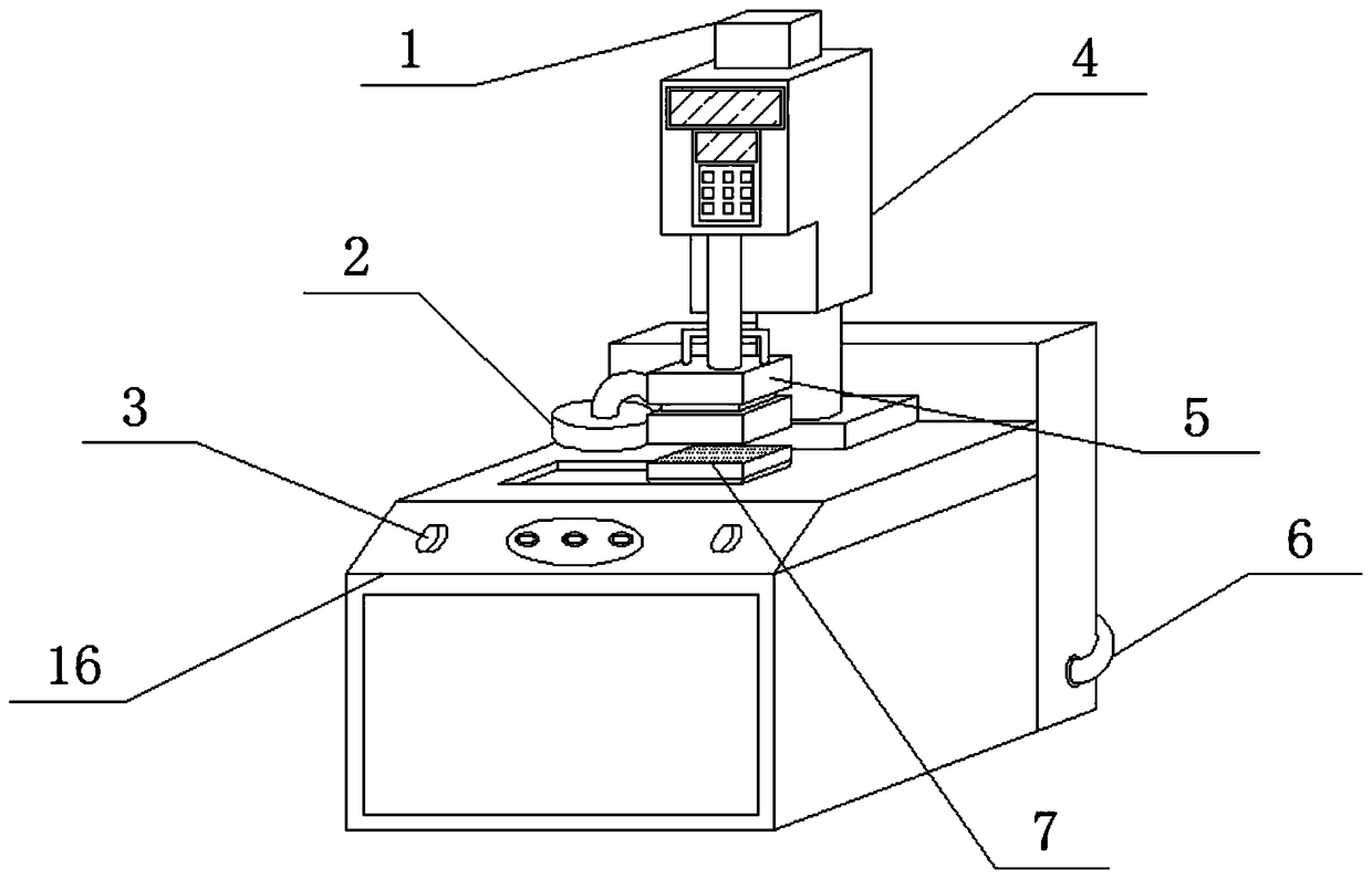
Ultrasonic hot drilling device with optical fiber laser lamp
A laser light and ultrasonic technology, applied in laser welding equipment, decorative art, manufacturing tools, etc., can solve the problems of lower work efficiency, difficulty in controlling strength for beginners, crushing of decorations, etc., to achieve reasonable design and improve ironing Efficiency and product quality, the effect of various functions
- Summary
- Abstract
- Description
- Claims
- Application Information
AI Technical Summary
Problems solved by technology
Method used
Image

Examples
Embodiment approach
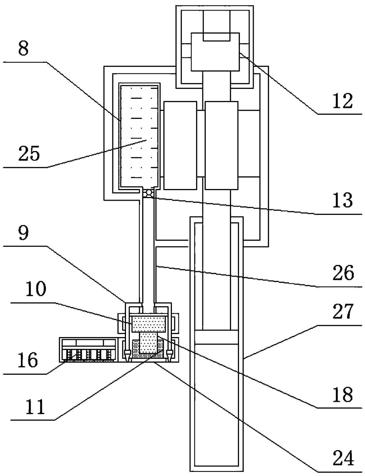
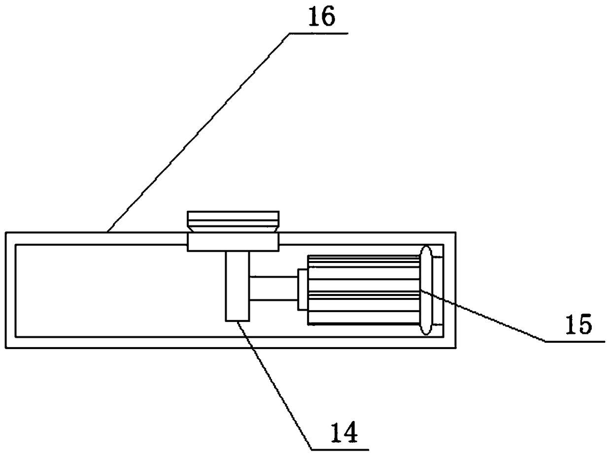
[0030] As a preferred embodiment of the present invention, the motor 15 is welded on the inner side wall of the base 16 through the motor base 2, the output shaft of the motor 15 is welded with a gear 14, and the base 16 has a mounting hole 5 , and the installation hole five is provided with a moving plate 17, the bottom of the moving plate 17 has an external gear, the moving plate 17 is installed on the gear 14 through the mutual cooperation of the external gear and the gear 14, and the moving plate 17 Welding socket 7 is arranged.
[0031] As a preferred embodiment of the present invention, one end of the telescopic rod 27 has a mounting hole 3, and the telescopic rod 27 is sleeved on the output shaft of the cylinder 12 through the mounting hole 3 .
[0032] As a preferred embodiment of the present invention, the control board 21 includes an intelligent processor 20 and a control switch 23, and the intelligent processor 20 includes a printed circuit main board and a micropro...
PUM
 Abstract
Description
Claims
Application Information
 - R&D Engineer
- R&D Manager
- IP Professional
- Industry Leading Data Capabilities
- Powerful AI technology
- Patent DNA Extraction
Browse by: Latest US Patents, China's latest patents, Technical Efficacy Thesaurus, Application Domain, Technology Topic, Popular Technical Reports.
© 2024 PatSnap. All rights reserved.Legal|Privacy policy|Modern Slavery Act Transparency Statement|Sitemap|About US| Contact US: help@patsnap.com