Method for testing high-cycle fatigue performance of engine fan blade

A technology of fan blades and testing methods, which is applied in the direction of engine testing, machine gear/transmission mechanism testing, and mechanical component testing, etc. Fully reflect the fatigue performance of fan blades and other issues, to achieve the effect of shortening the test time, improving reliability and increasing the test frequency

Active Publication Date: 2019-01-18
AVIC BEIJING AERONAUTICAL MFG TECH RES INST
View PDF7 Cites 11 Cited by
  • Summary
  • Abstract
  • Description
  • Claims
  • Application Information

AI Technical Summary

Problems solved by technology

It is assumed that the test of the engine fan blade test piece is carried out for 8 hours a day, and 3×10 7 The cycle test period is about 21 working days. To determine the fatigue performance of a certain type of engine fan blade, at least 15 fan blade test data are needed. Therefore, the total test period may be longer than 1 year. If 1×10 9 Cyclic test, the test cycle will be unacceptable;
[0007] On the other hand, in the fatigue test, the excitation frequency is the same as the first-order natural frequency of the engine fan blade. In the test, the clamping form with one end rigidly clamped and the other end free usually leads to bending deformation of the fan blade, and the maximum stress area of ​​deformation is usually close to the clamp. For advanced engine fan blades, the structure / material properties usually cannot meet the basic assumptions such as uniformity and consistency. Therefore, for this type of fan blades, the fatigue data based on one test point cannot fully reflect the overall performance of the fan blade. Fatigue performance

Method used


Image

  • Method for testing high-cycle fatigue performance of engine fan blade
  • Method for testing high-cycle fatigue performance of engine fan blade
  • Method for testing high-cycle fatigue performance of engine fan blade

Examples


Embodiment 1

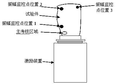
[0036] like Figure 1-10 As shown, a method for testing the high cycle fatigue performance of an engine fan blade comprises the following steps:

[0037] The first step is to design the fixture based on the geometric characteristics of the tenon of the engine fan blade, and rigidly fix the fan blade to the excitation device. The size is about 600mm, and the high rigidity fixture is designed and manufactured to fix the fan blades on the horizontal sliding table of the electromagnetic vibrating table;

[0038] In the second step, according to the natural frequency, vibration shape and stress distribution of the engine fan blade under the clamping condition of the software prediction test, according to the requirements of the fatigue performance assessment part and the stress distribution law obtained by calculation, the excitation frequency, vibration shape and stress distribution of the loading equipment are initially selected. The position of the amplitude monitoring point, t...


PUM


Abstract

The invention provides a method for testing the high-cycle fatigue performance of an engine fan blade, and relates to the technical field of structural mechanical performance tests. The technical point is that the inherent frequency of the engine fan blade is obtained by a sweep frequency test, and whether the vibration shape of the blade meets the test requirements is judged a phase relationshipbetween vibration data collected by sensors at different positions of the blade; and by adoption of the method provided by the invention, the vibration shape of the fan blade can be accurately judgedbased on a limited number of sensors, the test state of the fan blade can be accurately determined, the test frequency is improved, the test time is shortened, a plurality of check positions are provided for selection, the fatigue performance of the engine fan blade can be comprehensively evaluated, and the reliability in an external field service process is improved.

Description

technical field [0001] The invention relates to the technical field of structural mechanics performance testing, in particular to a method for testing the high-cycle fatigue performance of engine fan blades. Background technique [0002] Fatigue is one of the main failure modes of components, which causes huge economic losses every year. Aeroengine rotor blades work in a complex flow field and bear various external loads such as time-varying aerodynamic force and periodic mechanical excitation, which easily lead to fatigue cracks germination. my country's aviation turbojet engine failure statistics show that more than 70% of the failures are related to fatigue. Therefore, in order to improve the fatigue reliability of aero-engines, it is stipulated that sufficient fatigue performance tests should be carried out in the structural development process. Fatigue performance up to standard. [0003] The fatigue performance of parts is obtained through component-level fatigue perf...

Claims


Application Information

Patent Timeline
IPC IPC(8): G01M15/00G01M13/02
CPCG01M13/028G01M15/00
Inventor 邓瑛李志强邵杰韩晓宁张兴振
Owner AVIC BEIJING AERONAUTICAL MFG TECH RES INST
Why Eureka
Try Eureka