A DC bias characteristic test circuit and test method of a capacitor
A characteristic test, DC bias technology, applied in the field of electronics, can solve problems such as instrument burnout, and achieve the effect of eliminating shock, high test frequency and accurate numerical value
- Summary
- Abstract
- Description
- Claims
- Application Information
AI Technical Summary
Problems solved by technology
Method used
Image
Examples
Embodiment 1
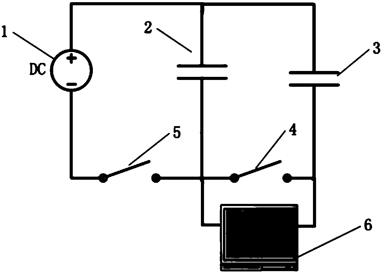
[0049] Embodiment 1: as figure 1 or figure 2 As shown, a DC bias characteristic testing circuit of a capacitor in the present invention includes a DC stabilized power supply 1, a test instrument 6, a first capacitive element 2, a second capacitive element 3, a first switch 5 and a second switch, so The positive pole of the DC stabilized power supply 1 is respectively connected to one end of the first capacitor 2 and one end of the second capacitor 3. The negative pole of the DC stabilized power supply 1 is connected to the other end of the first capacitor 2 through the first switch 5, and the first capacitor The other end of the component 2 is connected to the other end of the second capacitive component 3 through the second switch 4, the two measuring terminals of the test instrument 6 are connected to the two ends of the second switch 4, and the first capacitive component 2 is to be Measuring capacitance; The second capacitive element 3 is the same capacitance to be measur...
Embodiment 2
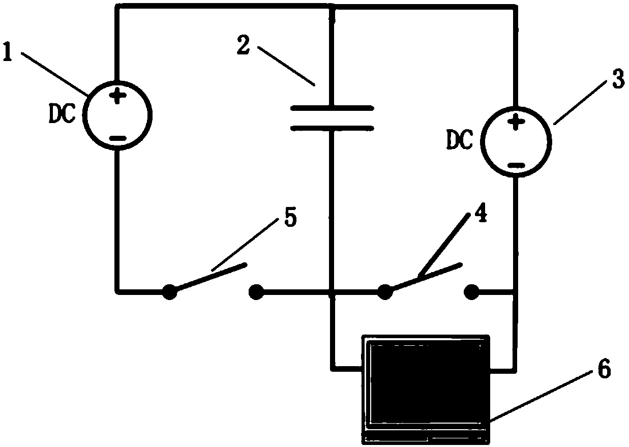
[0069] Such as image 3 As shown, a capacitor DC bias characteristic test circuit of the present invention includes a DC stabilized power supply 1, a test instrument 6, a first capacitive element 2, a second capacitive element 3, a first switch 5 and a second switch 4 The positive pole of the DC stabilized power supply 1 is respectively connected to one end of the first capacitive element 2 and one end of the second capacitive element 3. The negative pole of the DC stabilized voltage power supply 1 is connected to the other end of the first capacitive element 2 through the first switch 5, the second The other end of a capacitive element 2 is connected to the other end of the second capacitive element 3 through the second switch 4, and the two measuring terminals of the test instrument 6 are connected to the two ends of the second switch 4. The first capacitive element 2 is the capacitance to be measured; the second capacitive element 3 is a voltage source with known impedance....
Embodiment 3
[0088] Embodiment 3: as figure 1 As shown, a DC bias characteristic test circuit of a capacitor in the present invention includes a DC stabilized power supply 1, a test instrument 6, a first capacitive element 2, a second capacitive element 3, a first switch 5 and a second switch 4, The positive pole of the DC stabilized power supply 1 is respectively connected to one end of the first capacitive element 2 and one end of the second capacitive element 3. The negative pole of the DC stabilized voltage power supply 1 is connected to the other end of the first capacitive element 2 through the first switch 5. The other end of the capacitive element 2 is connected to the other end of the second capacitive element 3 through the second switch 4, the two measuring terminals of the test instrument 6 are connected to the two ends of the second switch 4, and the first capacitive element 2 is The capacitance to be measured; the second capacitance element 2 is a capacitance with known parame...
PUM
 Abstract
Description
Claims
Application Information
 - R&D
- Intellectual Property
- Life Sciences
- Materials
- Tech Scout
- Unparalleled Data Quality
- Higher Quality Content
- 60% Fewer Hallucinations
Browse by: Latest US Patents, China's latest patents, Technical Efficacy Thesaurus, Application Domain, Technology Topic, Popular Technical Reports.
© 2025 PatSnap. All rights reserved.Legal|Privacy policy|Modern Slavery Act Transparency Statement|Sitemap|About US| Contact US: help@patsnap.com


