Non-contact micro-cantilever beam rigidity measurement method based on electrostatic force

A measurement method, cantilever beam technology, applied in the direction of measuring devices, elastic testing, machine/structural component testing, etc., can solve the problems of uneven distribution of density and Young's modulus, cantilever beam measurement, etc., to avoid errors and the damage to the needle tip, the structure is simple and effective, and the effect of reducing uncertainty

Active Publication Date: 2019-01-18
TIANJIN UNIV
View PDF6 Cites 7 Cited by
  • Summary
  • Abstract
  • Description
  • Claims
  • Application Information

AI Technical Summary

Problems solved by technology

The three-dimensional method calculates the stiffness based on the size, density and Young's modulus of the beam. Due to the limitation of the processing technology and the existence of the gold-plated layer, the distribution of the density and Young's modulus of the beam is uneven, so the three-dimensional method usually has a large error ; The excitation of the thermal vibration method comes from the thermal motion of molecules. Due to the limitation of thermal noise energy, the thermal vibration method cannot measure the cantilever beam with high stiffness.

Method used


Image

  • Non-contact micro-cantilever beam rigidity measurement method based on electrostatic force
  • Non-contact micro-cantilever beam rigidity measurement method based on electrostatic force
  • Non-contact micro-cantilever beam rigidity measurement method based on electrostatic force

Examples


Embodiment 1

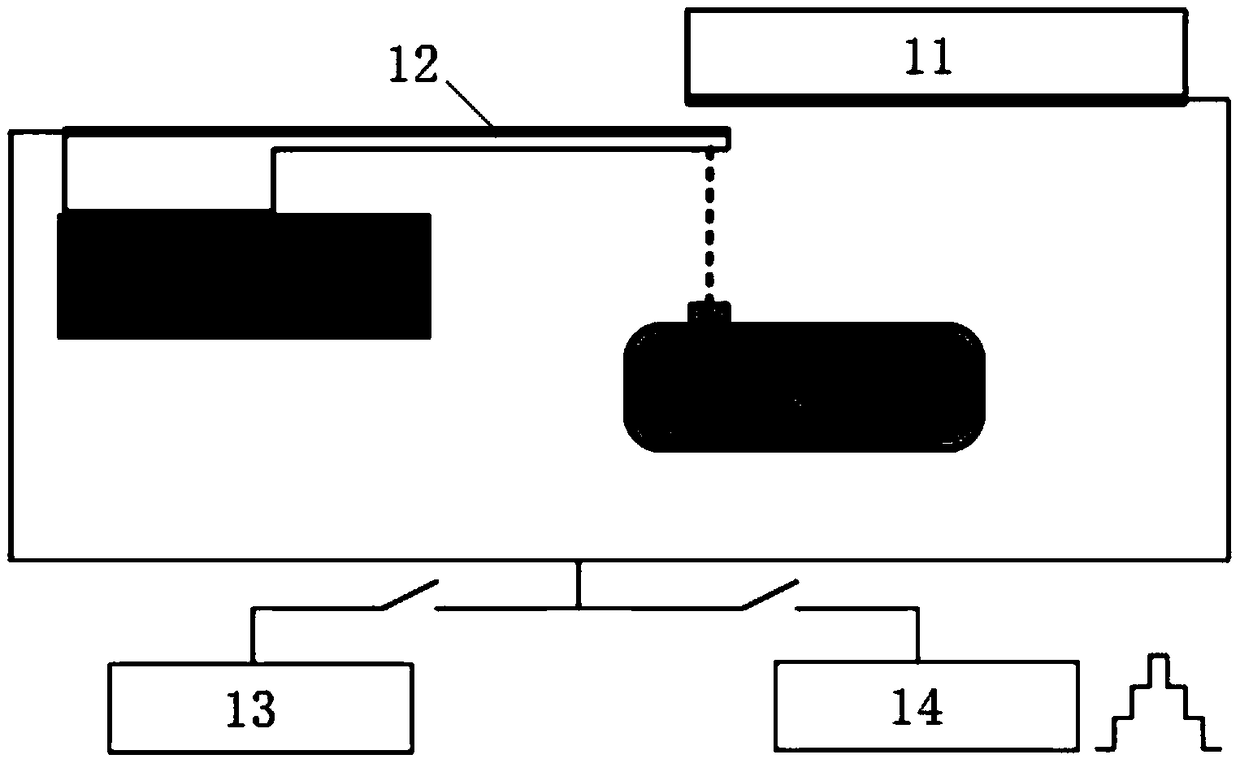
[0062] For example Figure 4a and Figure 4b The stiffness of a gold-coated microcantilever shown as 5 mm long, 0.5 mm wide, and 10 μm thick was measured.

[0063] After capacitance gradient measurement, capacitance gradient constant term A 1 The measured value and the slope k of each fitting line after stiffness fitting are shown in Table 1, and the measured value of stiffness is 0.3775N / m.

[0064] Table 1 capacitance gradient constant item A 1 and the measurement results of the cantilever beam stiffness k

[0065]


PUM


Abstract

The invention discloses a non-contact micro-cantilever beam rigidity measurement method based on an electrostatic force. The method comprises the following steps: establishing an experimental platform, controlling a nanometer micropositioner to drive a micro-cantilever beam to be tested to perform periodic equidistant stepping motion on a vertical direction, measuring a capacitance change betweenthe micro-cantilever beam to be tested and a plate electrode in real time by using a capacitance bridge, and performing mathematical treatment on the experimental data; and using a DC power source toload a periodic equidistant stepping voltage between the micro-cantilever beam to be tested and the plate electrode, using a laser interferometer to measure the displacement change of a free end of the micro-cantilever beam to be tested in real time, and performing mathematical treatment and fitting on the experimental data to obtain a rigidity measurement value of the micro-cantilever beam to betested. The non-contact micro-cantilever beam rigidity measurement method disclosed by the invention is based on the Hooke's law, the electrostatic force is used as the load, the nanometer micropositioner, the capacitance change, a stabilized voltage supply and the like are adopted, a micro-cantilever beam rigidity measurement platform is established, a mathematical relationship among the micro-cantilever beam rigidity, an interelectrode voltage and the displacement of the free end is established, and the non-contact measurement of the rigidity of the cantilever beam is achieved.

Description

technical field [0001] The invention relates to micro-nano testing and stiffness measurement, in particular to a non-contact micro-cantilever beam stiffness measurement method based on electrostatic force. Background technique [0002] Micro-cantilever beam, as the simplest MEMS structure, is a common tool for micro-nano testing and plays an extremely important role in the development of the micro-nano field. Due to its small size, low cost, and high sensitivity, microcantilever beams are widely used in many fields such as biological science, medical science, nanotechnology science, material science, surface science, and semiconductor industry. In the field of micro-nano testing, the surface characteristics or physical and chemical properties of the object to be tested are usually described by the deformation that occurs after the interaction between the micro-cantilever beam and the object to be tested, and the stiffness of the micro-cantilever beam is the key parameter. A...

Claims


Application Information

Patent Timeline
IPC IPC(8): G01M5/00
CPCG01M5/0083G01N2203/0003G01N2203/0019G01N2203/005G01N2203/0075G01N2203/0676G01N2203/0682
Inventor 赵美蓉王志一郑叶龙黄银国
Owner TIANJIN UNIV
Why Eureka
Try Eureka