
Airtight platform anchoring device

A platform anchor and airtight technology, applied in the direction of shipping equipment, etc., can solve the problems that it is difficult to avoid the entry of salt water vapor into the fan platform, the anchoring of the submarine cable platform does not have airtight performance, and the installation is complicated, so as to achieve temporary fixation , protection from corrosion, good sealing effect

Pending Publication Date: 2019-01-18
ZHONGTIAN TECH MARINE SYST CO LTD
View PDF0 Cites 4 Cited by
  • Summary
  • Abstract
  • Description
  • Claims
  • Application Information

AI Technical Summary

Problems solved by technology

[0005] 2. In order to solve the problem of temporarily fixing the submarine cable after it enters the platform, temporary clamps can be used to temporarily fix the submarine cable. At present, the commonly used temporary clamps mainly use the Haval-shaped metal clamp to hold the submarine cable tightly. Complicated and needs to be customized according to the specification of the submarine cable
[0006] 3. For the fan foundation with single-pile entry type, the flange through hole where the submarine cable enters the platform directly communicates with the seawater at the bottom of the tower, and the brine vapor formed by the heating and evaporation of seawater can enter the flange of the platform along the submarine cable The through hole enters the platform, which affects the safety of electronic components inside the platform; the anchorage of the submarine cable platform at this stage does not have airtight performance from the design structure, and it is difficult to avoid the salt water vapor in the single pile hole type fan tower entering the fan platform internal

Method used


Image

  • Airtight platform anchoring device
  • Airtight platform anchoring device
  • Airtight platform anchoring device

Examples


Embodiment Construction

[0024] The present invention will be described in further detail below through examples, and the following examples are explanations of the present invention and the present invention is not limited to the following examples.

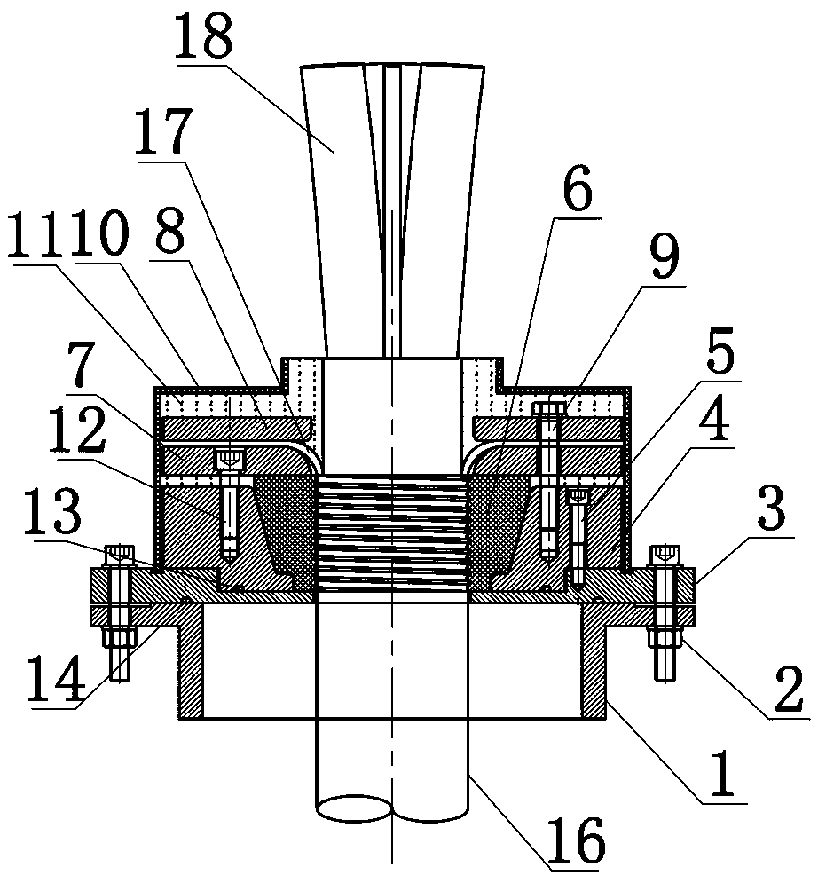
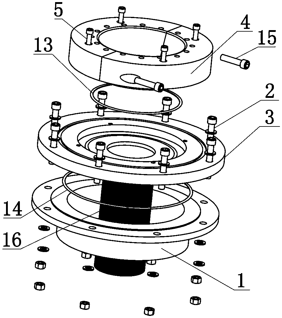
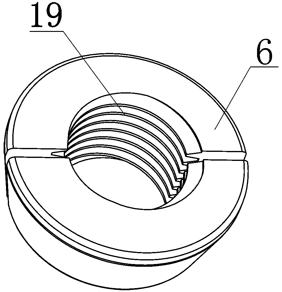
[0025] Such as figure 1 , 2 , 3, and 4, a kind of airtight platform anchoring device of the present invention comprises base 3, ring seat 4, PU temporary clip 6, backing plate 7, pressure plate 8 and outer cover 10, base 3 shape and platform top The flange 1 is matched and detachably fixed on the upper side of the flange 1 at the top of the platform, the ring seat 4 is detachably fixed on the upper side of the base 3 and there is a circular truncated through hole in the ring seat 4 that matches the shape of the PU temporary clip 6, PU The outer side of the temporary clip 6 is a truncated cone and is set in the through hole of the ring seat 4. The backing plate 7 is set on the upper side of the PU temporary clip 6 and the backing plate 7 is detachably f...


PUM


Abstract

The invention discloses an airtight platform anchoring device. The device comprises a base, a ring seat, a PU temporary clamp, a backing plate, a pressure plate and a cover. The base shape is matchedwith a platform top flange and is detachably fixed to the upper side of the platform top flange, the ring seat is detachably fixed to the upper side of the base, a truncated-type through hole matchedwith the shape of the PU temporary clamp is formed in the ring seat, the outer side of the PU temporary clamp is a truncated type and is arranged in the through hole of the ring seat, the backing plate is disposed on the upper portion of the PU temporary clamp, the backing plate is detachably fixed to the ring seat, the pressure plate is disposed on the upper side of the backing plate and is detachably fixed to the backing plate and the ring seat, the cover is disposed outside the ring seat, the backing plate and the pressure plate, and the lower end of the cover is fixed to the upper side ofthe base. The device integrates the temporary clamp into the platform anchoring device, and not only achieves the temporary fixing effect of the lightweight temporary clamp on a submarine cable, but also achieves the airtightness of the inside of platform anchoring.

Description

technical field [0001] The invention relates to an anchoring device, in particular to an airtight platform anchoring device. Background technique [0002] The invention is applicable to the field of cable fixing. Offshore wind power generation and offshore oil and gas platforms mainly realize power transmission with the outside world through submarine cables. Safe and stable fixing of large-quality submarine cables on platforms is a prerequisite for stable operation of submarine cables. At present, the main way to fix the submarine cable on the platform is to clamp the clamp with threaded fasteners, and then clamp the armored steel wire of the submarine cable. The static friction between the armored steel wire and the clamp is greater than the self-weight of the submarine cable. Cable fixing. [0003] The above common method of fixing the submarine cable on the platform has the following problems: [0004] 1. At present, the commonly used Haval platform platform anchoring ...

Claims


Application Information

Patent Timeline
IPC IPC(8): E02B3/24
CPCE02B3/24
Inventor 陈磊董吴磊吴金峰郭朝阳谢书鸿蔡炳余
Owner ZHONGTIAN TECH MARINE SYST CO LTD
Learn More