Novel hollow slab funnel hinge joint structure and construction method thereof

A construction method and technology of hollow slabs, which are applied to bridge parts, erection/assembly bridges, bridges, etc., can solve problems such as low tensile capacity, veneer stress, and bottom mortar falling off, so as to improve shear strength and bending resistance ability, improve shear strength, and enhance the overall effect

Inactive Publication Date: 2019-01-18
GUANGDONG UNIV OF TECH
View PDF0 Cites 4 Cited by
  • Summary
  • Abstract
  • Description
  • Claims
  • Application Information

AI Technical Summary

Problems solved by technology

These huge number of hollow slab girder bridges have also exposed many problems during decades of operation and use. Among them, the more concentrated and more harmful problems are water seepage and whitening at the bottom of the hinge joints, falling off of the bottom mortar, and longitudinal cracking. In particular, the funnel hinge joints are small and have low tensile capacity, so they are easy to be damaged, forming single-plate stress, and cannot play a good role in horizontal connection. The entire hollow slab bridge is not rigid enough, and the integrity of the bridge is poor.
This kind of disease has almost become a common problem of most prefabricated hollow slab girder bridges. They will have many adverse effects on this type of bridge structure, affecting the service life of the bridge, deteriorating the operating state of the bridge, and even endangering the driving safety in severe cases.
In addition, road management and maintenance departments in various places have to invest a lot of money every year to repair such diseases, but they still cannot cure these problems

Method used


Image

  • Novel hollow slab funnel hinge joint structure and construction method thereof
  • Novel hollow slab funnel hinge joint structure and construction method thereof
  • Novel hollow slab funnel hinge joint structure and construction method thereof

Examples


Embodiment

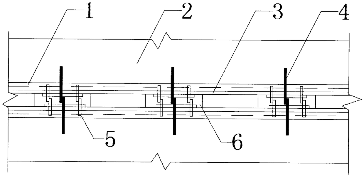
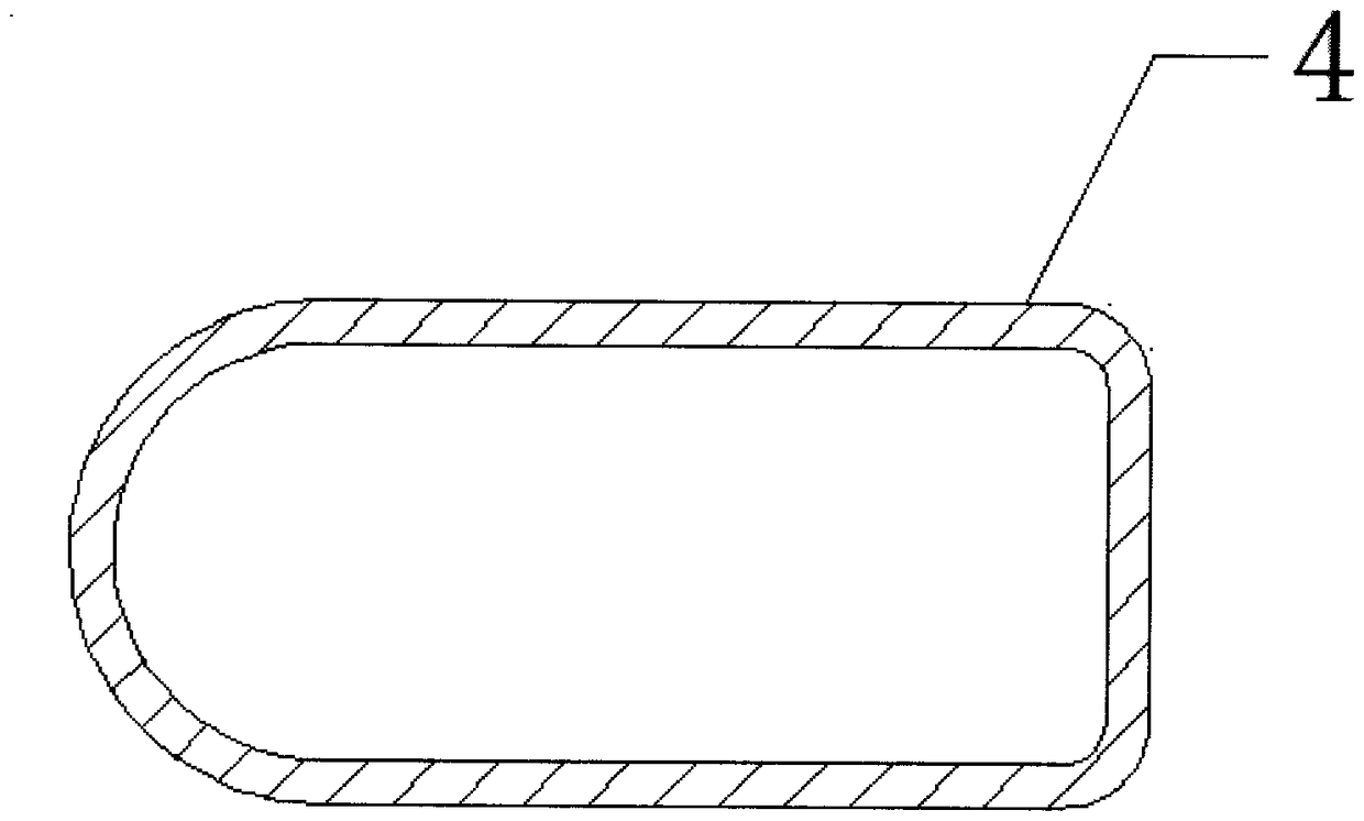
[0023] Example: such as Figure 1-3 As shown, a novel hollow slab funnel hinge joint structure, the structural system is mainly composed of prefabricated hollow slabs (1) spliced ​​longitudinally on the same plane, and funnel hinge joints (3) are formed between the prefabricated hollow slabs (1), The prefabricated hollow slab (1) and hinged joints (3) are poured with concrete pavement (2), the prefabricated hollow slab (1) is pre-embedded with closed U-shaped steel bars (4), and the adjacent prefabricated hollow The closed U-shaped steel bar (4) pre-buried in the plate (1) extends into the upper part of the funnel hinge (3) and overlaps each other. Corrugated steel connectors. The corrugated steel plate connector comprises a corrugated steel plate (6) and a connecting bolt (5), the corrugated steel plate (6) is respectively connected with the prefabricated hollow plate (1) through the connecting bolt (5), and the straight plate sections on both sides of the corrugated steel p...


PUM


Abstract

The invention discloses a novel hollow slab funnel hinge joint structure and a construction method thereof, and belongs to the technical field of bridge structure design. The structural system is mainly composed of prefabricated hollow slabs which are longitudinally spliced together in the same plane, The concrete pavement layer is composed of a pre-embedded closed U-shaped steel bar and a corrugated steel plate connector, wherein the corrugated steel plate connector comprises a corrugated steel plate and a connecting bolt; the corrugated steel plate is respectively connected with a prefabricated hollow plate through the connecting bolt; and the connecting bolt is a friction type high-strength bolt. The embedded U-shaped reinforcing bar can effectively improve the strength of the joint surface of the prefabricated hollow slab and the hinge joint, the corrugated steel plate connector can improve the shear strength and bending resistance of the joint, It also enhances the integrity of hollow slabs and hinge joints, and overcomes the shortcomings of low tensile strength of hinge joints of domestic assembled hollow slab bridges, easy cracking, not playing a very good role in transverseconnection, insufficient rigidity of the whole hollow slab bridge, and poor integrity of bridges.

Description

technical field [0001] The invention belongs to the technical field of bridge structure design and relates to a novel hollow slab funnel hinge joint structure and a construction method thereof. Background technique [0002] Highway bridges are an important part of the highway traffic system, among which there are a large number of small and medium-span bridges, accounting for the vast majority. With the development of society and economy, the load levels of vehicles are very different from those in the past. The design load levels of some earlier highway bridges have been difficult to adapt to the current vehicle loads, which has caused a series of bridge damage and disease problem. Moreover, with the increase of the service life of bridges, the disease problems of some small and medium-span bridges have become more and more serious, and they are showing a trend of concentrated outbreaks. [0003] Among the hundreds of thousands of small and medium-span highway bridges in ...

Claims


Application Information

Patent Timeline
Patent Type & Authority Applications(China)
IPC IPC(8): E01D19/06E01D21/00
CPCE01D19/067E01D21/00
Inventor 王添龙姜海波
Owner GUANGDONG UNIV OF TECH
Why Eureka
Try Eureka