
Airport luggage conveying rack

A technology for conveying racks and luggage, which is applied to mechanical conveyors, conveyors, conveyor objects, etc., can solve the problems of large luggage conveying racks, serious surface friction, inconvenient processing, etc., and achieves stable operation, compact structure, and long and highly scalable effects

Pending Publication Date: 2019-01-18
信华智能装备(江苏)有限公司
View PDF0 Cites 0 Cited by
  • Summary
  • Abstract
  • Description
  • Claims
  • Application Information

AI Technical Summary

Problems solved by technology

[0002] The airport baggage conveying device is an important part of the airport. The airport adopts the mode of separating large luggage from the passengers. The function of airport baggage conveying must be timely, accurate, safe and efficient. Most of the currently used airport baggage conveying devices are conveyor structures. , by placing the luggage on the conveyor belt, the motor rotates to drive the conveyor belt to move, and the luggage is transported to the corresponding height or designated position. Due to the large amount of luggage at the airport, a sorter, laser scanning system, and luggage monitoring system are installed at the same time , the alarm system makes the airport luggage conveyor rack huge, inconvenient to process, and heavy to move, and the airport luggage conveyor line has been in use for a long time, the surface friction is serious, the paint is easy to fall off, and it needs to be replaced in time, which brings trouble to the airport transportation, and the airport luggage The system is separated from the people, and the outbound baggage conveying line and the arriving baggage conveying line are respectively set up. The baggage conveying route is long. Therefore, the present invention provides an airport baggage conveying rack, which adopts a modular operation mode, so that the luggage conveying rack line The length and height can be adjusted freely, the length can be expanded freely, and the height can also be expanded, so as to meet the special needs of long airport lines

Method used


Image

  • Airport luggage conveying rack
  • Airport luggage conveying rack

Examples


Embodiment Construction

[0017] The preferred embodiments of the present invention will be described in detail below in conjunction with the accompanying drawings, so that the advantages and features of the present invention can be more easily understood by those skilled in the art, so as to define the protection scope of the present invention more clearly.

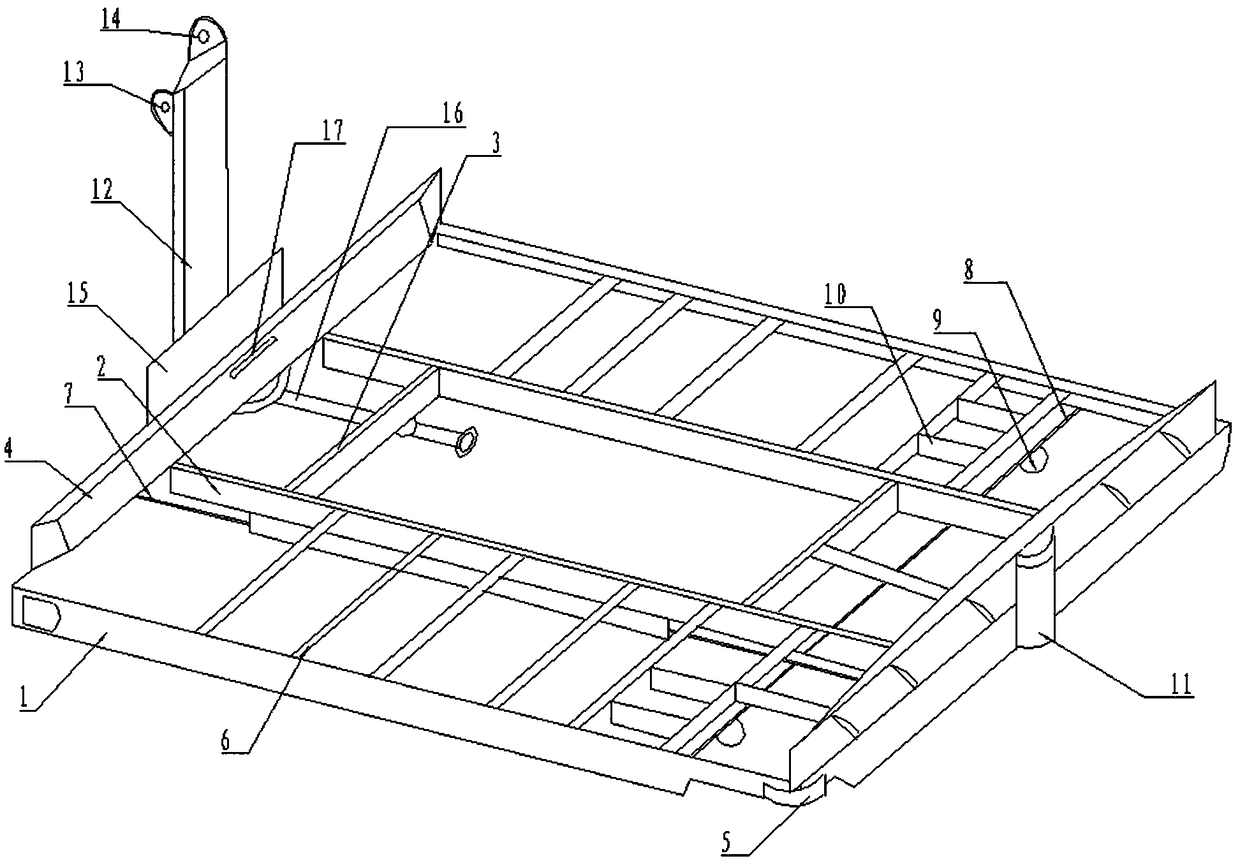
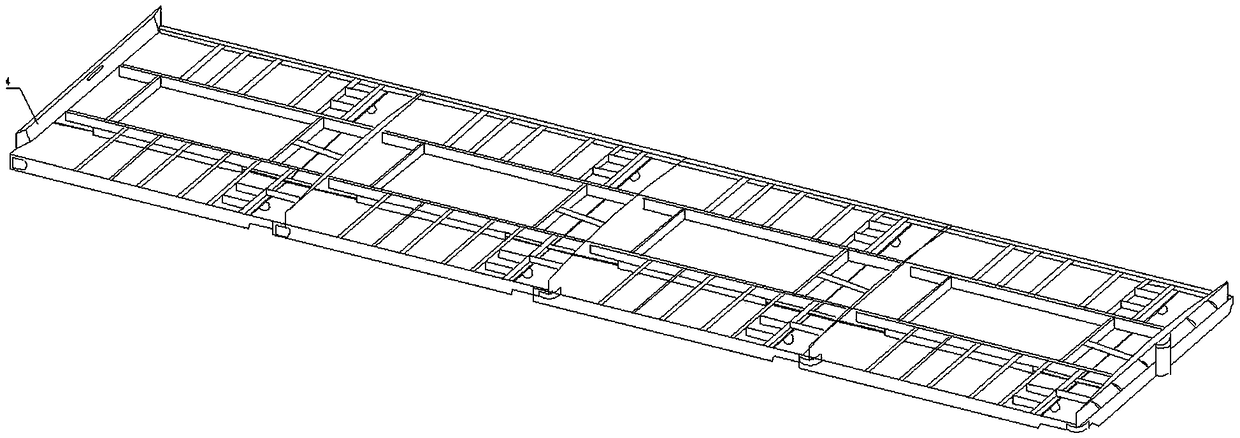
[0018] see figure 1 , figure 2 , the embodiment of the present invention includes:

[0019] figure 1 It is a reverse bottom view of an airport luggage conveyor rack.

[0020] The airport luggage conveyor rack includes: an end beam bracket, the end beam bracket adopts a cuboid structure, and the end beam bracket is made of stainless steel or cast iron material, wherein the number of end beam brackets is 4, forming a word shape, Between two adjacent end beam brackets, they are connected together by rivets.

[0021] Two intermediate brackets are set between the mouth-shaped end beams. The intermediate brackets are cuboid structures. A cross bar...


PUM


Abstract

The invention discloses an airport luggage conveying rack comprising four end beam support frames that form a square shape, two middle support frames are arranged between end beams that form the square shape, a cross rod is arranged between the two middle support frames and is connected with a lengthwise leg part fixing rod, bottom part support seats are arranged on the end beam support frames, four to eight round roller support frames are arranged between the end beam support frames and the middle support frames, and rolling cylinders are arranged on the round roller support frames. The airport luggage conveying rack disclosed in the invention is compact in structure, stable in equipment operation, long in service life, convenient in assembling operation and convenient in length and height expansion.

Description

technical field [0001] The invention relates to the technical field of airport baggage conveying equipment, in particular to an airport baggage conveying rack. Background technique [0002] The airport baggage conveying device is an important part of the airport. The airport adopts the mode of separating large luggage from the passengers. The function of airport baggage conveying must be timely, accurate, safe and efficient. Most of the currently used airport baggage conveying devices are conveyor structures. , by placing the luggage on the conveyor belt, the motor rotates to drive the conveyor belt to move, and the luggage is transported to the corresponding height or designated position. Due to the large amount of luggage at the airport, a sorter, laser scanning system, and luggage monitoring system are installed at the same time , the alarm system makes the airport luggage conveyor rack huge, inconvenient to process, and heavy to move, and the airport luggage conveyor lin...

Claims


Application Information

Patent Timeline
Patent Type & Authority Applications(China)
IPC IPC(8): B65G37/00B65G21/00B65G41/00
CPCB65G21/00B65G37/00B65G41/00
Inventor 高超
Owner 信华智能装备(江苏)有限公司
Learn More