
Manual label making machine with continuous printing function

A labeling machine and label paper technology, applied in typewriters, printing, metal processing, etc., can solve the problems of inconvenient installation of full-cut blades, blunt life of full-cut blades, and easy skew of label paper cuts, etc., to achieve simple and convenient assembly , save manpower and material waste, and facilitate the cutting effect

Pending Publication Date: 2019-01-18
BEIJING SUPVAN ELECTRONIC TECH CO LTD
View PDF0 Cites 2 Cited by
  • Summary
  • Abstract
  • Description
  • Claims
  • Application Information

AI Technical Summary

Problems solved by technology

The above structure has the following defects: (1) After the label printing is completed, the paper feeding mechanism always sends out a section (about 20mm) of blank label paper for subsequent printing, resulting in waste of label paper; (2) It is not conducive to cutting , the incision of the label paper is easy to skew, the edge is not neatly cut, and even the phenomenon of continuous cutting occurs; (3) the full-cut blade is easy to blunt and has a short life; (4) the full-cut blade is inconvenient to install, resulting in waste of manpower and materials
In view of the above defect (1), if a continuous printing label machine is used, no blank space can be realized, but how to simply and efficiently control the start and stop of the printing head and the paper feeding mechanism is also a technical difficulty

Method used


Image

  • Manual label making machine with continuous printing function
  • Manual label making machine with continuous printing function
  • Manual label making machine with continuous printing function

Examples


Embodiment Construction

[0032] The technical solutions of the present invention will be clearly and completely described below in conjunction with the accompanying drawings. Apparently, the described embodiments are some of the embodiments of the present invention, but not all of them. Based on the embodiments of the present invention, all other embodiments obtained by persons of ordinary skill in the art without making creative efforts belong to the protection scope of the present invention.

[0033] In the description of the present invention, it should be noted that the orientation or positional relationship indicated by the terms "upper", "lower", "front", "rear" etc. is based on the orientation or positional relationship shown in the drawings, and is only for It is convenient to describe the present invention and simplify the description, but does not indicate or imply that the device or element referred to must have a specific orientation, be constructed and operate in a specific orientation, an...


PUM


Abstract

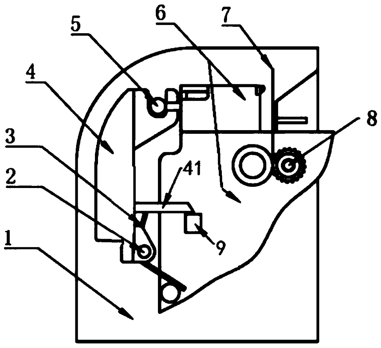
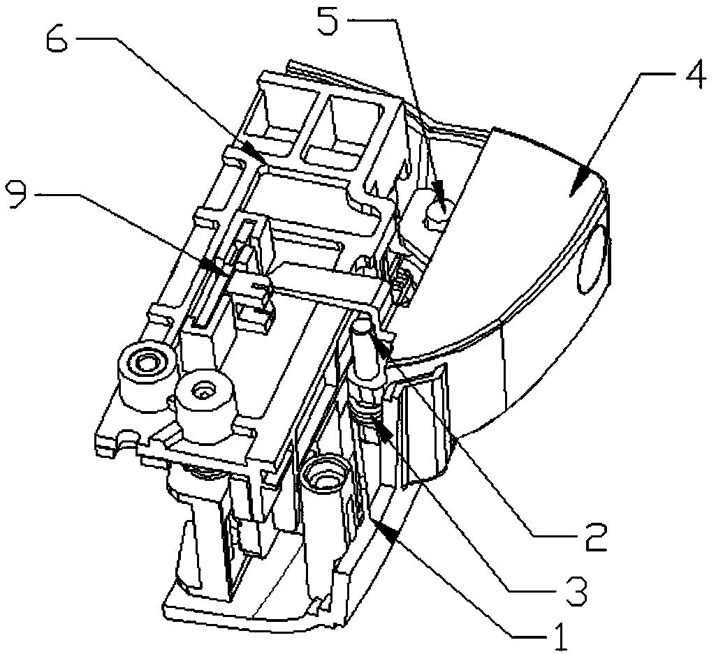
The invention discloses a manual label making machine with a continuous printing function. The manual label making machine comprises a housing, a full cutting button is installed on the housing, the full cutting button is connected with a full cutting knife assembly, an extension arm is connected to the full cutting button, and a photoelectric detection switch area is arranged in the housing; whenthe full cutting button is pressed to start label paper cutting, the extension arm enters the photoelectric detection switch area under the driving of the full cutting button; when the full cutting button resets after label paper cutting, the extension arm leaves the photoelectric detection switch area under the driving of the full cutting button. In the manual label making machine, through the cooperation of the extension arm arranged on the full cutting button and the photoelectric detection switch area, start and stop of a paper feeding mechanism and a printing head of the label marking machine can be controlled according to signals sent when the extension arm enters and exits from the photoelectric detection switch area, then, the label marking machine can perform printing without blanks, and the waste of the label paper can be reduced. Besides, through structural improvement on the full cutting knife assembly, cutting is facilitated, the phenomena of skew, deckle edges and the like of cuts of the label paper do not occur easily, and the manual label making machine is suitable for application and popularization.

Description

technical field [0001] The invention relates to the field of printers, in particular to a continuous printing manual labeling machine. Background technique [0002] A labeler is a printer used to print logos on labels. The existing labeling machine comprises a housing and a core board installed in the housing. A paper feeding mechanism and a full cutter assembly that can move back and forth on the core board are installed on the core board. The full cutter assembly includes a knife rest and The full-cut blade installed on the knife holder is fixed by screws, and the cutting edge of the full-cut blade is a commonly used straight-edge cutting edge. When working, the paper feeding mechanism installed on the core board clamps and sends out the label paper. After the length of the label paper reaches the predetermined printing length, the full cutting operation can be performed. The full cutting knife assembly slides on the core board to drive The full-cut blade moves forward a...

Claims


Application Information

Patent Timeline
Patent Type & Authority Applications(China)
IPC IPC(8): B26D7/02B26D7/08B26D1/06B26D7/26B26D5/00B41J3/407
CPCB26D1/0006B26D1/065B26D5/00B26D7/025B26D7/08B26D7/2614B41J3/4075B26D2001/0053
Inventor 李建国李海平王建华
Owner BEIJING SUPVAN ELECTRONIC TECH CO LTD
Learn More