New energy vehicle battery box

A technology of new energy vehicles and battery packs, which is applied to battery pack components, batteries, circuits, etc., and can solve problems such as car failures and damages

Inactive Publication Date: 2019-01-15
SUZHOU UNIV OF SCI & TECH
View PDF0 Cites 3 Cited by
  • Summary
  • Abstract
  • Description
  • Claims
  • Application Information

AI Technical Summary

Problems solved by technology

[0003] The existing technology is to simply fix the battery pack on the car with screws and nuts. As the car runs, the battery pack may collide with the mounting parts on the car and cause damage, thereby causing car failure

Method used


Image

  • New energy vehicle battery box
  • New energy vehicle battery box

Examples


Embodiment 1

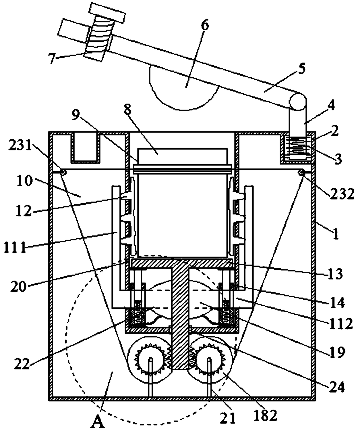
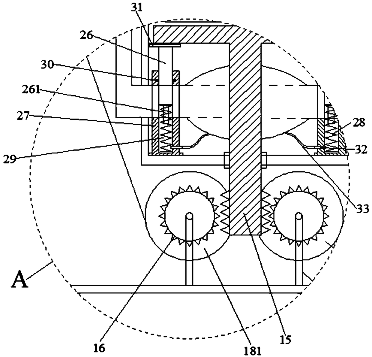
[0024] Embodiment 1: A battery pack box for new energy vehicles, including an installation box body 1, a battery pack 8, a cover plate 5, an elastic rope 10, a main airbag 19 and several side airbags 12, the installation box body 1 The upper part has an upward opening storage chamber 20, the battery pack 8 is located in the storage chamber 20, a support plate 13 is located below the battery pack 8 and contacts its lower surface, and a lifting rod 15 is installed on the lower surface of the support plate 1313, so that A sliding sleeve 24 is arranged between the lifting rod 15 and the through hole at the bottom of the storage chamber 20, and at least three elastic mechanisms 14 are arranged at equal intervals around the lifting rod 15 between the support plate 13 and the bottom of the storage chamber 20. 14 further includes a piston rod 26, a cylindrical base 27 and a first spring 28. The lower part of the piston rod 26 is embedded in the central hole of the cylindrical base 27 t...

Embodiment 2

[0033] Embodiment 2: A battery pack box for new energy vehicles, including an installation box body 1, a battery pack 8, a cover plate 5, an elastic rope 10, a main airbag 19 and several side airbags 12, the installation box body 1 The upper part has an upward opening storage chamber 20, the battery pack 8 is located in the storage chamber 20, a support plate 13 is located below the battery pack 8 and contacts its lower surface, and a lifting rod 15 is installed on the lower surface of the support plate 1313, so that A sliding sleeve 24 is arranged between the lifting rod 15 and the through hole at the bottom of the storage chamber 20, and at least three elastic mechanisms 14 are arranged at equal intervals around the lifting rod 15 between the support plate 13 and the bottom of the storage chamber 20. 14 further includes a piston rod 26, a cylindrical base 27 and a first spring 28. The lower part of the piston rod 26 is embedded in the central hole of the cylindrical base 27 t...


PUM


Abstract

The invention discloses a new energy vehicle battery box, comprises a mounting box body, a battery pack, a cover plate, an elastic rope, a main air bag and a plurality of side air bags, wherein the upper part of the mounting box body is provided with an upwardly-opened storage cavity, the battery pack is positioned in the storage cavity, a support plate is positioned below the battery pack and isin contact with the lower surface thereof, and a lifting rod is mounted on the lower surface of the support plate; An upper surface of that mount box is respectively provided with an mount groove anda threaded hole on both sides of the object chamber, and one end of the cover plate is mounted to one end of the mounting box body through a through hole inner strut embedded in the mounting groove; At least two pair of guide bumps and guide groove are symmetrically arranged between that support plate and the mounting box body, so that the support plate can slide along the side wall of the mounting box body; The elastic rope winds around the upper part of the battery pack, and a rubber ring is arranged between the elastic rope and the battery pack. The new energy vehicle battery box reduces the rigid collision in the driving process of the automobile, enhances the air pressure given to the side airbag, and greatly reduces the rigid collision in the driving process of the automobile.

Description

technical field [0001] The invention relates to the technical field of automobiles, in particular to a battery pack box for new energy vehicles. Background technique [0002] With the development of the new energy automobile industry, the use of new energy vehicles is becoming more and more common in people's daily life. During the battery installation process, battery assembly is an essential processing procedure. After the battery assembly is completed, The battery needs to be fixed to ensure that the battery has high stability. [0003] The prior art is to simply fix the battery pack on the car with screws and nuts. As the car runs, the battery pack may collide with the mounting parts on the car and cause damage, thereby causing car failure. Contents of the invention [0004] The purpose of the present invention is to provide a battery pack box for new energy vehicles, the battery pack box for new energy vehicles fixes the position of the battery pack, so that there is...

Claims


Application Information

Patent Timeline
Patent Type & Authority Applications(China)
IPC IPC(8): H01M2/10H01M50/249
CPCH01M2220/20H01M50/20Y02E60/10
Inventor 葛丽娟
Owner SUZHOU UNIV OF SCI & TECH
Why Eureka
Try Eureka