
An ultraviolet LED quartz lens assembly structure and method

A quartz lens and assembly structure technology, applied in electrical components, circuits, semiconductor devices, etc., can solve problems such as increased production costs, strict vacuum requirements, lens shedding, etc., to improve work efficiency, increase contact surface, Applicable effect

Pending Publication Date: 2019-01-15
SHANGHAI UVPRO
View PDF0 Cites 4 Cited by
  • Summary
  • Abstract
  • Description
  • Claims
  • Application Information

AI Technical Summary

Problems solved by technology

[0005] B. Due to the porous structure of silica gel, the silica gel lens is exposed outside, and it is easy to absorb dust and debris during actual production, assembly and use. After lighting, a high temperature hot spot will be formed on the lens surface until the lens burns out;
[0006] C. The adhesion between the silica gel and the LED bracket is insufficient, and the lens is prone to fall off during the wiping and cleaning process;
[0007] D. High-viscosity silica gel has poor fluidity and strict vacuuming requirements, which increases manufacturing costs;
[0008] E. The UV transmittance of silica gel is low, which reduces the light output efficiency of LED chips

Method used


Image

  • An ultraviolet LED quartz lens assembly structure and method
  • An ultraviolet LED quartz lens assembly structure and method
  • An ultraviolet LED quartz lens assembly structure and method

Examples


Embodiment Construction

[0031] The present invention will be further described below in conjunction with the drawings:

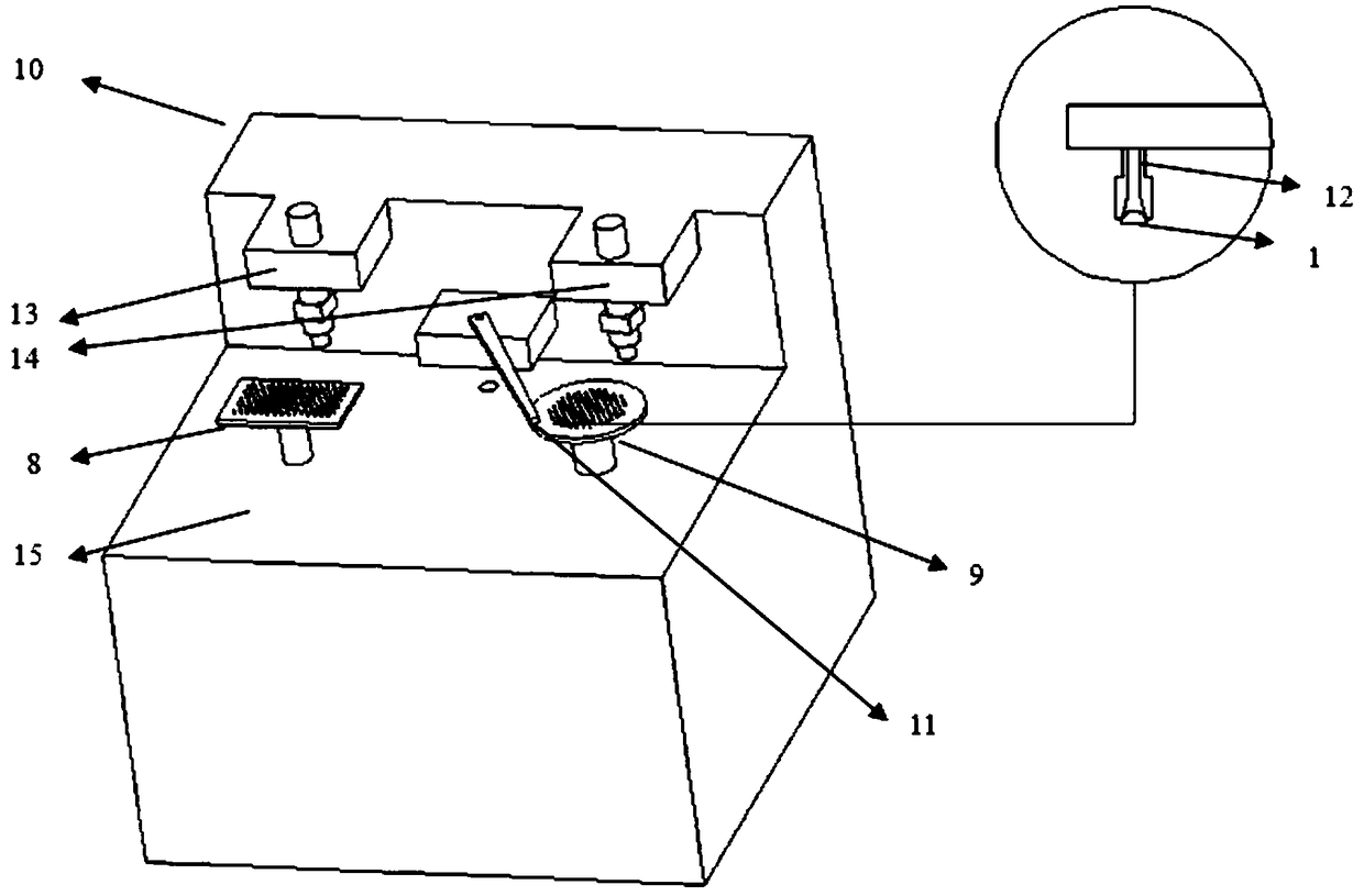
[0032] The present invention includes an LED bracket 8 and a lens ring 9. The LED bracket 8 and the lens ring 9 are respectively arranged on the left and right sides of the front part of the dispensing workbench 15 of the die bonding machine 10. The LED bracket 8 is packaged with an ultraviolet LED chip 2 and a lens. Hemispherical quartz lenses 1 are arranged in an array on the ring 9, a swing arm mounting seat is provided at the center of the back of the glue dispensing work table 15 of the die bonder 10, and a swing arm 11 is rotatably connected to the swing arm mounting seat. The other end of the swing arm 11 is equipped with a suction nozzle 12. The suction nozzle 12 is made of hard plastic. The suction nozzle 12 is designed as a conical opening. The LED bracket 8 and the lens ring 9 are respectively equipped with a CCD camera 13 and a CCD camera. Two 14: CCD camera one 13 and CCD...


PUM


Abstract

The invention relates to an ultraviolet LED quartz lens assembly structure, include an LED support, Lens ring, LED holder, A lens ring is respectively arrange on that left side of the front part of the dispensing table of the crystal fixing machine, At that right side, an ultraviolet LED chip is package on the LED bracket, A lens array on that lens re is arranged with quartz lenses, A swing arm isrotatably connected at that central position of the rear part of the dispensing table of the crystal fix, A suction nozzle is arrange at that other end of the swing arm, the suction nozzle is designas a conical opening, an LED bracket, a CCD camera is respectively arranged above the lens re, the swing arm recognizes an image through the CCD camera and finds a lens center point on the lens ring,and then the quartz lens is placed on an ultraviolet LED chip through the CCD camera; As compare with that prior art, the invention improves the work efficiency by changing the arrangement of the suction nozzle and designing the lens array, replace the manual work by a machine, and enlarges the contact surface between the suction nozzle and the lens through the conical opening of the suction nozzle, so as to ensure the sufficient adsorption capacity.

Description

[Technical Field] [0001] The invention relates to the technical field of LED packaging, in particular to an ultraviolet LED quartz lens assembly structure and method. [Background technique] [0002] As a new green and environmentally friendly industry, UV LED will gradually replace traditional UV lamps with the advantages of long service life, small size, low energy consumption and the entry into force of the "Minamata Convention". [0003] At present, the UV LED uses Molding (injection molding) process. After the die bonding process is completed on the LED bracket, it is fixed in position with the lens mold, and then high-viscosity silicone is injected into the lens mold cavity and vacuumed, and placed together Bake in the oven to form the silicone lens, the main disadvantages are as follows: [0004] A. Generally, hot-press molded silica gel contains epoxy resin, which is not resistant to UV and high temperature. It is easy to crack and yellow during use, which greatly reduces the...

Claims


Application Information

Patent Timeline
IPC IPC(8): H01L33/58H01L33/56H01L21/683
CPCH01L33/56H01L33/58H01L21/6838H01L2933/0058
Inventor 姜杰张炜孙斌
Owner SHANGHAI UVPRO
Learn More