
Gate structure and methods thereof

A gate dielectric and metal gate technology, applied in the field of gate structure and its formation, can solve problems such as not proving that the existing process is completely satisfactory

Active Publication Date: 2019-01-15
TAIWAN SEMICON MFG CO LTD
View PDF6 Cites 2 Cited by
  • Summary
  • Abstract
  • Description
  • Claims
  • Application Information

AI Technical Summary

Problems solved by technology

[0004] Therefore, the existing process has not proven to be completely satisfactory in all respects

Method used


Image

  • Gate structure and methods thereof
  • Gate structure and methods thereof
  • Gate structure and methods thereof

Examples


Embodiment Construction

[0015] The following disclosure provides many different embodiments or examples for implementing different features of the presented subject matter. Specific examples of components and arrangements are described below to simplify the present disclosure. Of course, these are examples only and are not intended to limit the invention. For example, in the following description, forming a first component over or on a second component may include an embodiment in which the first component and the second component are formed in direct contact, and may also include an embodiment in which the first component and the second component are formed in direct contact. An embodiment in which an additional component may be formed between such that the first component and the second component may not be in direct contact. In addition, the present invention may repeat reference numerals and / or characters in various instances. This repetition is for the sake of simplicity and clarity and does n...


PUM


Abstract

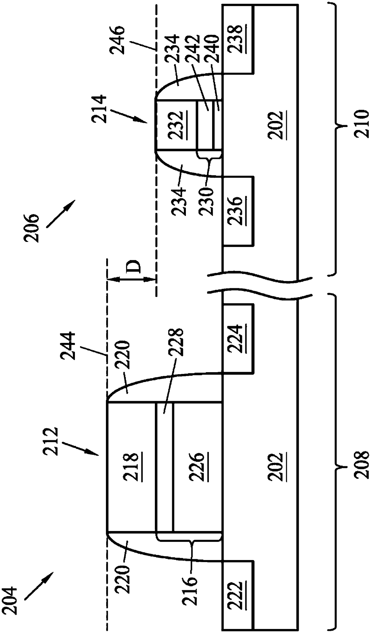
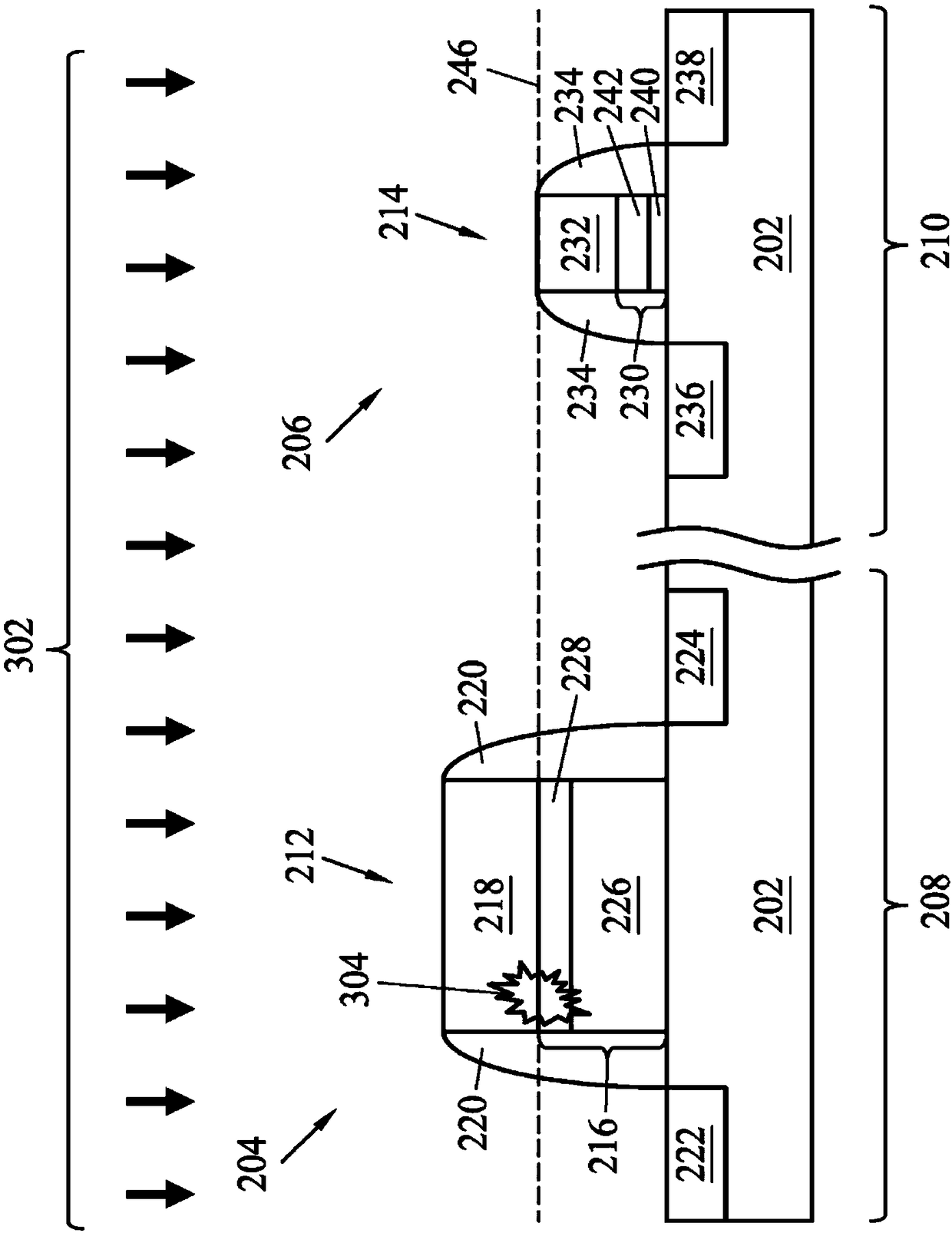
The embodiment of the invention relates to a method and structure that provide a high-voltage transistor (HVT) including a gate dielectric, where at least part of the gate dielectric is provided within a trench disposed within a substrate. In some aspects, a gate oxide thickness may be controlled by way of a trench depth. By providing the HVT with a gate dielectric formed within a trench, embodiments of the present disclosure provide for the top gate stack surface of the HVT and the top gate stack surface of a low-voltage transistor (LVT), formed on the same substrate, to be substantially co-planar with each other, while providing a thick gate oxide for the HVTs. Further, because the top gate stack surface of HVT and the top gate stack surface of the LVT are substantially co-planar with each other, over polishing of the HVT gate stack can be avoided.

Description

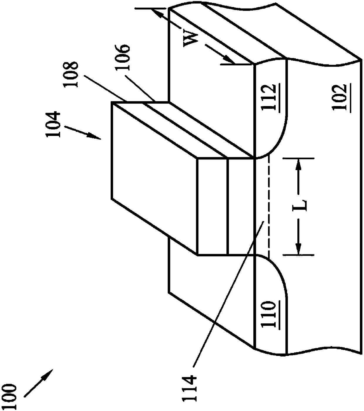
technical field [0001] Embodiments of the present invention generally relate to the field of semiconductors, and more particularly, to gate structures and methods of forming the same. Background technique [0002] The electronics industry has experienced a growing demand for smaller and faster electronic devices capable of simultaneously supporting more and more increasingly complex and refined functions. Accordingly, there is a continuing trend in the semiconductor industry to manufacture integrated circuits (ICs) that are low cost, high performance, and low power consumption. To date, these goals have been largely achieved by scaling down semiconductor IC dimensions (eg, minimum feature size), and thus increasing production efficiency and reducing associated costs. However, this scaling down also creates an increased complexity of the semiconductor fabrication process. Accordingly, achieving continued advances in semiconductor ICs and devices requires similar advances in...

Claims


Application Information

Patent Timeline
Patent Type & Authority Applications(China)
IPC IPC(8): H01L21/28H01L21/336H01L29/423H01L29/78H10N97/00
CPCH01L29/401H01L29/4236H01L29/42364H01L29/66621H01L29/78H01L21/823814H01L21/823857H01L21/823878H03K19/018521H01L27/0922H01L28/40H01L29/66492H01L21/32055H01L21/3213H01L21/304H01L21/31051H01L29/66484H01L21/823481H01L21/823462
Inventor 郑安皓郭舫廷
Owner TAIWAN SEMICON MFG CO LTD
Learn More